Injection molding machine

a molding machine and injection molding technology, applied in the field of injection molding machines, to achieve the effect of preventing damage to the lighting, prolonging the life of the lighting, and reducing the damage to the lighting

Active Publication Date: 2016-04-28
FANUC LTD
View PDF1 Cites 1 Cited by
  • Summary
  • Abstract
  • Description
  • Claims
  • Application Information

AI Technical Summary

Benefits of technology

[0024]Lighting is provided if needed even when the operator intends to, since the lighting is turned on and off automatically and inter-connectedly with back and forward motion of the injection unit. Thus the work is performed smoothly and the operator does not forget to turn off the lighting.
[0025]The present invention, with the configuration mentioned above, securely lightens the interior portion of the resin scattering preventing cover and the mold touching portion, without preventing the opening and closing of the resin scattering preventing cover since the lighting is attached such that the lighting is configured to be moved interlocking with the resin scattering preventing cover, configured to be lightened. In addition to that, the lighting is set not preventing work of the operator by being attached easily detachably from the resin scattering preventing cover, such that the restriction of the arrangement of the lighting unit is released.
[0026]The lighting is attached outside the resin scattering preventing cover for protecting the lighting from the heat or the molten resin, such that damage of the lighting is prevented. Furthermore, the lighting is lightened without waste and the lifetime of the lighting is elongated, since the lighting is configured to be turned on and off interlockedly with the forward and backward movement of the injection unit.

Problems solved by technology

The resin scattering preventing cover configured to open and close includes the lighting unit configured to lighten the mold touching portion and the internal portion of the resin scattering preventing cover in the lighting unit, and the attached lighting unit, interlocked with the resin scattering preventing cover, does not prevent opening / closing motion of the resin scattering preventing cover.

Method used


Image

  • Injection molding machine
  • Injection molding machine
  • Injection molding machine

Examples


Embodiment Construction

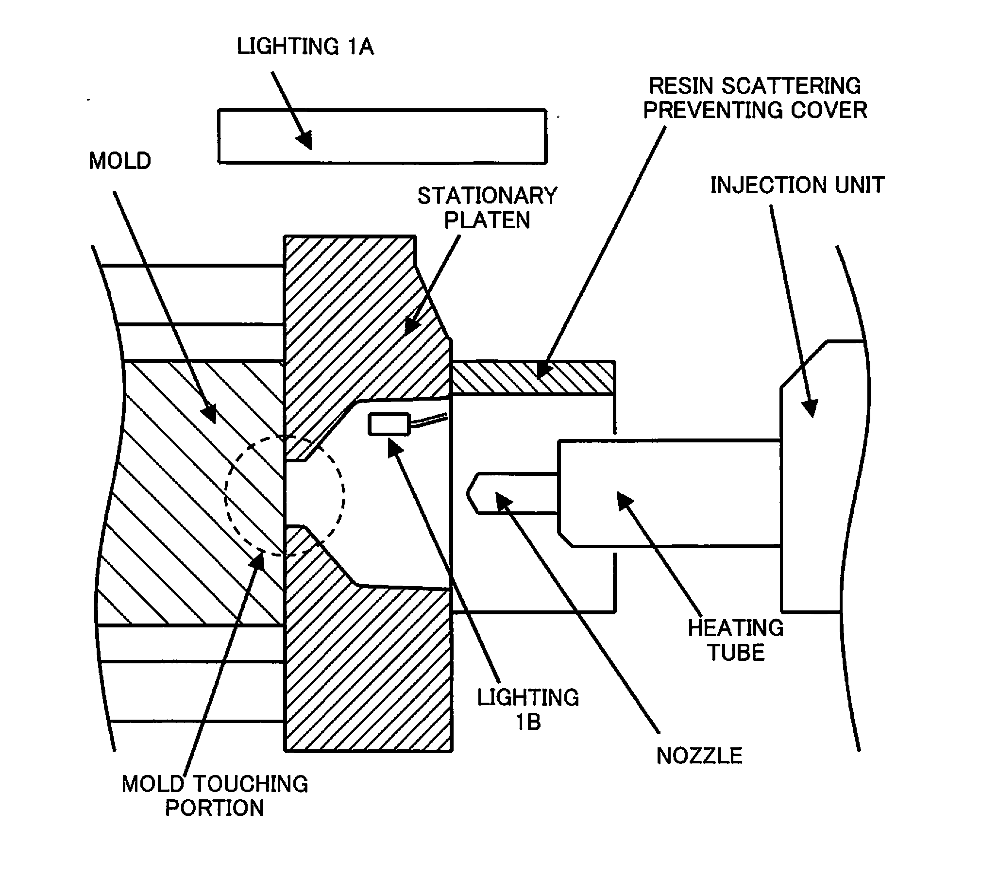
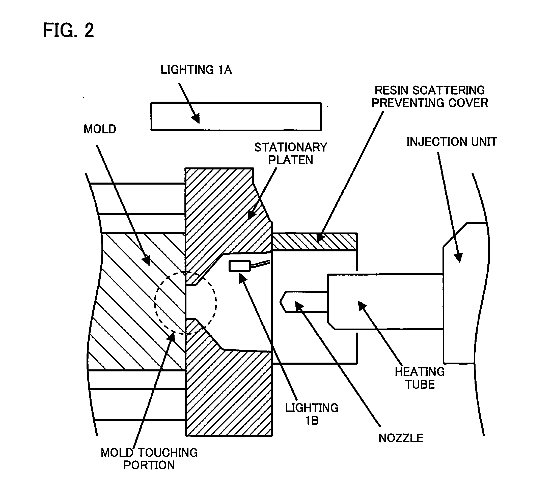
[0034]As shown in FIGS. 3, 4, and 5, resin scattering prevention covers 2A, 2B are attached to an injection molding machine. A lighting 1 fixed to a lighting fixing part is attached outside of the resin scattering prevention cover 2B, installed such that the resin scattering prevention cover 2B is opened and closed using a hinge 3A. Light of the lighting 1 is configured to lighten the mold touching portion and the interior portion of the resin scattering preventing cover 2B through a window having a transparent plate, installed in the resin scattering preventing cover 2B. When the lighting is attached in the direction the resin scattering preventing cover 2B opens, there is a case where the lighting prevent opening and closing of the resin scattering preventing cover 2B. However, the lighting 1 is attached movably to the resin scattering preventing cover 2B by connecting the lighting fixing part and the resin scattering preventing cover 2B using the hinge 3B, such that the lighting ...


PUM

PropertyMeasurementUnit
areaaaaaaaaaaa
residual pressureaaaaaaaaaa
transparentaaaaaaaaaa

Abstract

An injection molding machine includes a resin scattering preventing cover configured to prevent resin scattering from injection nozzle fixed to an end of an injection unit, a lighting unit configured to molding contact portion where the injection nozzle and a mold contact, a fixing unit configured to fix the lighting unit, and an opening/closing portion where the resin scattering prevention cover is configured to open and close; wherein the fixing unit is connected interlocked with opening and closing of the opening/closing portion.

Description

BACKGROUND OF THE INVENTION[0001]1. Field of the Invention[0002]The present invention relates to an injection molding machine, and more specifically to a resin scattering preventing cover providing lighting to around a nozzle and molding touching portion.[0003]2. Description of the Related Art[0004]Purge of resin in a heating tube is performed when an injection molding machine is stopped, color is changed, or resin is changed, during injection molding. There is a possibility that the resin is popped out from the end of the nozzle, influenced by gas in the heating tube or release of residual pressure, since the purge is performed while the top end of the nozzle does not touch the mold. Therefore, there is an injection molding machine in which a resin scattering preventing cover, covering the top end of the nozzle for protecting the operator from the scattering of the resin, is attached. The resin scattering preventing cover is usually attached to a stationary platen with configuratio...

Claims


Application Information

Patent Timeline
Patent Type & Authority Applications(United States)
IPC IPC(8): B29C45/64
CPCB29C45/64B29C45/03B29C45/17B29C2045/1784B29C2045/1797B29C45/1753B29C45/1777B29C45/84
Inventor OHSHIRO, KATSUFUMI
Owner FANUC LTD
Why Eureka
Try Eureka