

Display system with extended display area
a display system and display area technology, applied in the field of video displays and headmounted displays, can solve the problems of less light reaching and unused lens coverage areas, and achieve the effect of more ligh
- Summary
- Abstract
- Description
- Claims
- Application Information
AI Technical Summary
Benefits of technology
Problems solved by technology
Method used
Image

Examples
Embodiment Construction
[0001]Embodiments of the present disclosure relate generally to video displays, head-mounted displays and, more specifically, to a display system with an extended active display area.
Description of the Related Art
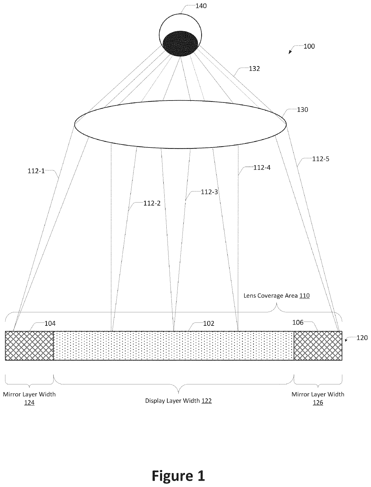
[0002]An optical assembly includes a display assembly and a lens. During operation, the display assembly generates an image by causing pixels included in the display assembly to emit light rays that propagate to the lens. The lens concentrates light rays provided by the display assembly, where the concentrated light rays reach the eye of the user.
[0003]The lens has an associated lens coverage area. The lens coverage area of the lens is the area of a particular plane, parallel to the lens at a given distance, which the user can see through the lens. The lens coverage area is based on the configuration of the lens, a distance between the lens and a particular plane, and the field of view of the user, which is distance between the lens and the plane of the user's eye. In some ...
PUM
| Property | Measurement | Unit |
|---|---|---|
| quarter-wavelength | aaaaa | aaaaa |
| area | aaaaa | aaaaa |
| distance | aaaaa | aaaaa |
Abstract
Description
Claims
Application Information