Lighting device and luminaire

a technology of light source and light source, which is applied in the direction of lighting apparatus, electrical equipment, light sources, etc., can solve the problems of output electric current deviating from a rated value, buck converter components having delay time, and buck converter technique cannot improve the electric current variation, etc., to achieve stable lighting up, suppress the variation of light output of these elements, and simple configuration

Active Publication Date: 2015-02-05
PANASONIC INTELLECTUAL PROPERTY MANAGEMENT CO LTD
View PDF4 Cites 9 Cited by
  • Summary
  • Abstract
  • Description
  • Claims
  • Application Information

AI Technical Summary

Benefits of technology

[0011]The present invention has been made bearing the foregoing in mind, and it is an object of the present invention to provide a lighting device that is operated by the BCM control and the peak current control, and capable of stably lighting up solid-state light-emitting elements having different properties while suppressing variations in light output of these elements with a simple configuration.
[0013]Herein, the delay circuit may generate the delay time so that a peak value of the electric current flowing through the inductor is kept constant regardless of the voltage detected by the voltage detection circuit.
[0015]Moreover, the delay circuit may generate a minimum delay time as the delay time when the forward voltage of the solid-state light-emitting element connected to the lighting device is at a minimum value Vout_min, where Vout_min denotes a minimum value of the forward voltage of the solid-state light-emitting element to be connected to the lighting device.
[0021]One aspect of the present invention achieves a lighting device that is operated by the BCM control and the peak current control, and capable of stably lighting up solid-state light-emitting elements having different properties while suppressing variations in light output of these elements with a simple configuration, and a luminaire including the lighting device.

Problems solved by technology

However, components constituting the buck converter have a delay time (for example, a delay time of a detection operation circuit, a signal output delay time of a driver IC, a drive delay time of the switching element, etc.).
However, the techniques in Japanese Unexamined Patent Application Publications No. 2012-109141 and No. 2010-40509 described above have the following problems.
Thus, such a technique cannot improve the electric current variations at the time of variations in output voltage due to the delay time.
Further, when different kinds of loads (namely, LEDs) having the same current rating and different voltage ratings are connected or when the number of loads connected in series is changed, it is also conceivable that the difference in output voltage may cause the output electric current to deviate from a rated value, and thus a desired light output cannot be obtained.
However, since the error amplifier and peripheral circuits are necessary for constituting the feedback circuit, the cost of circuit components increases.
Thus, there arises a significant stress and loss, for example, a through-current flows through the components such as the switching elements of the buck converter in order to switch ON / OFF the continuous electric current.
This lowers a circuit efficiency, raises the cost of circuit components and increases a circuit size.
The above-described technique is not suitable especially for high-power illumination uses.

Method used


Image

  • Lighting device and luminaire
  • Lighting device and luminaire
  • Lighting device and luminaire

Examples


embodiment 1

[0039]First, a lighting device according to Embodiment 1 of the present invention will be described.

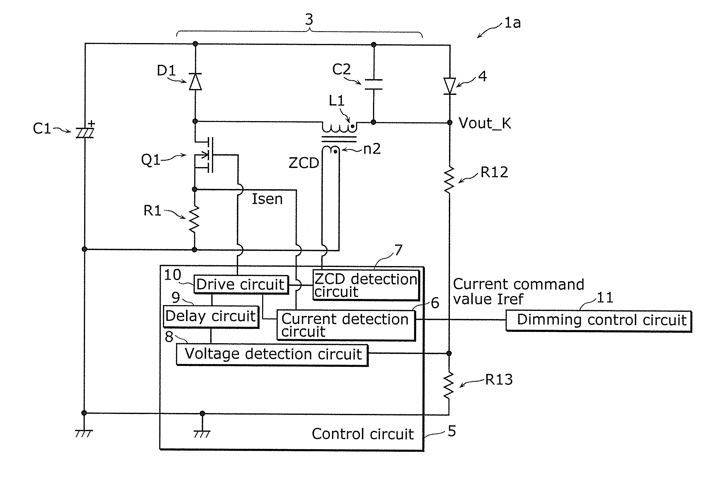
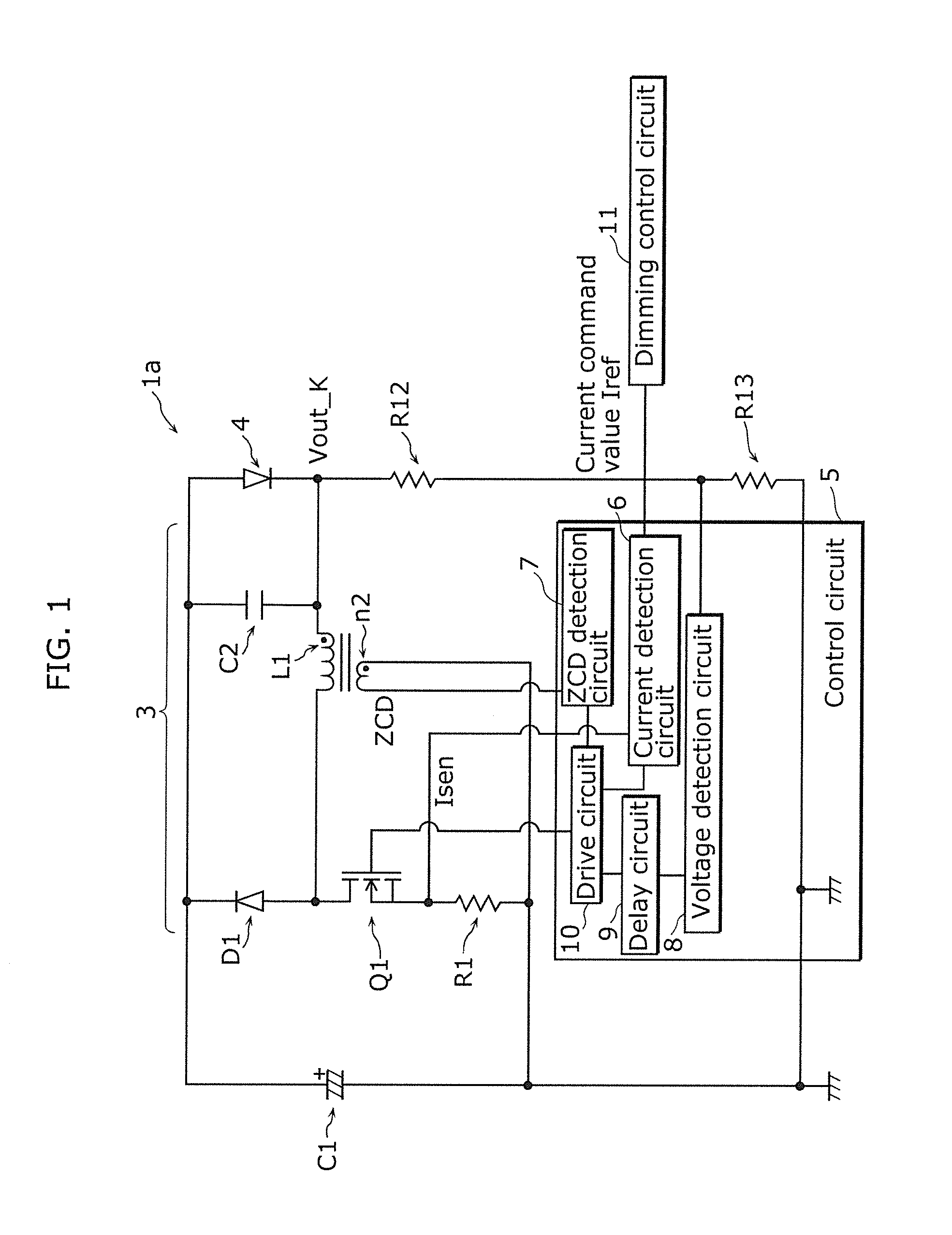
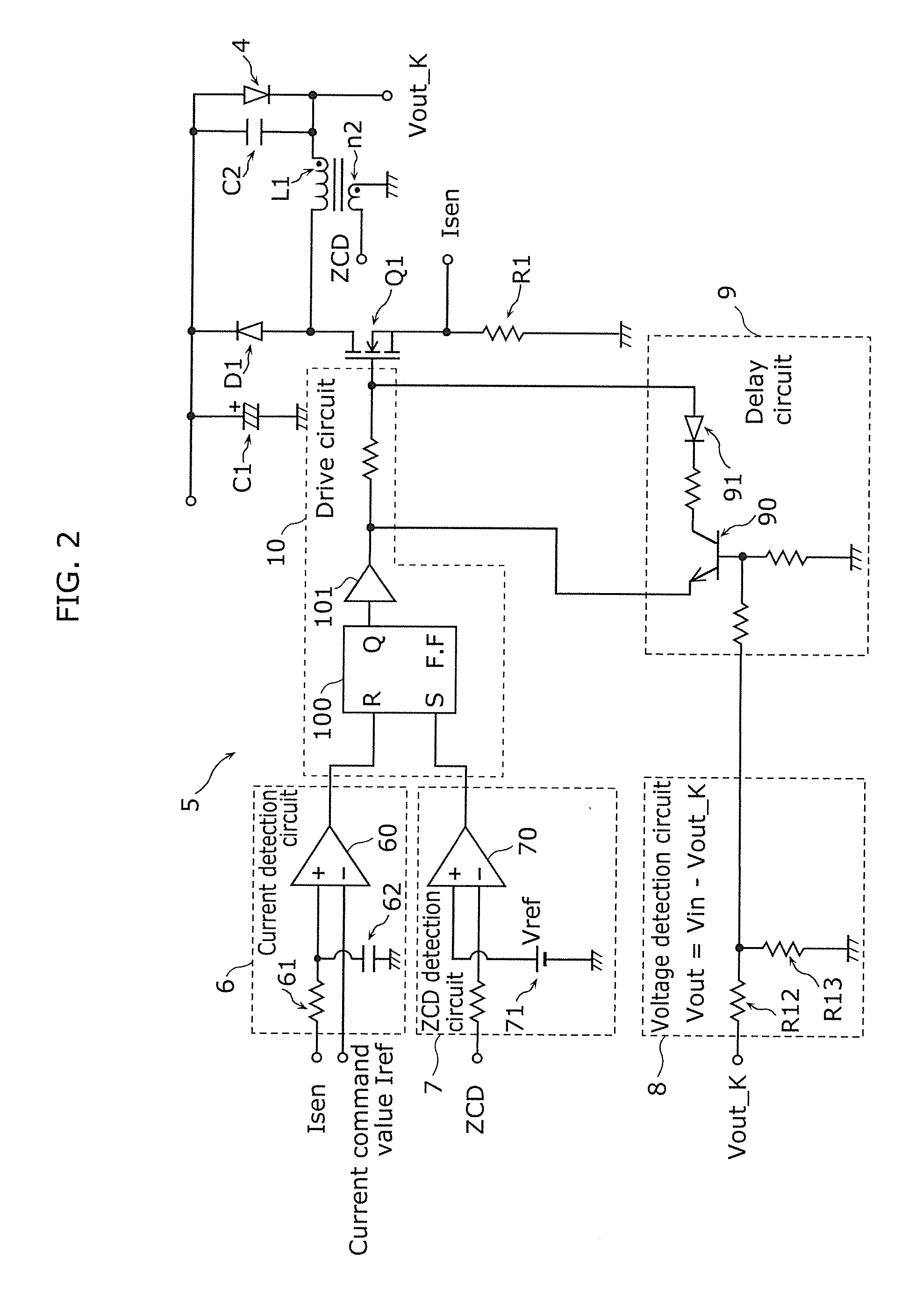
[0040]FIG. 1 is a circuit diagram of a lighting device 1a in Embodiment 1 of the present invention, and FIG. 2 is a detailed circuit diagram of a control circuit 5 included in the lighting device 1a. This technique is different from a background art in that a delay circuit 9 is added in the control circuit 5.

[0041]The lighting device 1a is a device for lighting up an LED 4, which is an example of a solid-state light-emitting element serving as a load, and includes a smoothing capacitor C1 serving as a DC power source, a buck converter 3, the control circuit 5 for controlling the buck converter 3, and a dimming control circuit 11. The buck converter 3 is a constant current output converter that receives an electric current from the smoothing capacitor C1 serving as a DC power source and supplies a predetermined electric current to the LED 4. In other words, this lighting device 1a incl...

embodiment 2

[0087]Next, a lighting device according to Embodiment 2 of the present invention will be described.

[0088]Embodiment 2 is different from Embodiment 1 in the configuration of the buck converter and part of the control circuit. However, the basic operation of the buck converter in Embodiment 2 is similar to that in Embodiment 1. Thus, the following description of Embodiment 2 will be directed only to the difference from Embodiment 1.

[0089]In Embodiment 1, the method of changing the speed of extracting a gate-source electric charge of the switching element Q1 has been discussed as the method for generating the delay time by the delay circuit 9. However, with such a method, there is a possibility that the generated delay time might vary due to component-to-component variations in the threshold voltage, gate capacity and so on of the switching element Q1.

[0090]Accordingly, the present embodiment will illustrate a delay circuit that can generate an accurate delay time with reduced variatio...

embodiment 3

[0102]Next, a lighting device according to Embodiment 3 of the present invention will be described.

[0103]Embodiment 3 is different from Embodiments 1 and 2 in that plural sets of a buck converter, a control circuit and a solid-state light-emitting element (here, an LED) are provided.

[0104]FIG. 10 is a circuit diagram of a lighting device 1c in Embodiment 3. This lighting device 1c includes a plurality of buck converters 3a to 3c for stepping down a DC voltage of the smoothing capacitor C1 serving as a common DC power source and supplying a DC current to LEDs 4a to 4c serving as loads, and a plurality of control circuits 5a to 5c. The present embodiment will be described using a circuit including three buck converters 3a to 3c and three control circuits 5a to 5c.

[0105]Each of the buck converters 3a to 3c has a circuit configuration similar to the buck converter 3 in Embodiment 1. For example, the buck converter 3a includes an inductor L1a, a switching element Q1a, a diode D1a and an...


PUM


Abstract

A lighting device that lights up an LED and includes a DC power source, a buck converter and a control circuit. The buck converter includes a switching element, an inductor and a diode. The control circuit includes a current detection circuit that detects an electric current flowing through the switching element, a voltage detection circuit that detects a voltage across the inductor, a delay circuit that generates a delay time according to the voltage detected by the voltage detection circuit, and a drive circuit that generates and outputs a control signal to the switching element, the control signal turning OFF the switching element after a lapse of the delay time generated by the delay circuit from when the electric current detected by the current detection circuit reaches a predetermined current command value.

Description

CROSS REFERENCE TO RELATED APPLICATION[0001]This application claims the benefit of priority of Japanese Patent Application Number 2013-161861, filed Aug. 2, 2013, the entire content of which is hereby incorporated by reference.TECHNICAL FIELD[0002]The disclosure relates to a lighting device that lights up a solid-state light-emitting element such as an LED, and a luminaire including the lighting device.BACKGROUND ART[0003]Desirably, a lighting device that stably lights up LEDs (light emitting diodes) serving as loads should be under constant current control, which outputs a constant output electric current for any load. The reason is as follows: the voltage-current characteristics of an LED element have a non-linear feature in which an electric current starts flowing suddenly at a certain applied voltage or higher, a forward voltage does not substantially change while an electric current near a rated current value is flowing, and light output basically depends on a value of an elect...

Claims


Application Information

Patent Timeline
Patent Type & Authority Applications(United States)
IPC IPC(8): H05B33/08H05B44/00
CPCH05B33/0815H05B45/3725H05B45/375
Inventor YAMAHARA, DAISUKEKAMOI, TAKESHISEKI, KEISUKE
Owner PANASONIC INTELLECTUAL PROPERTY MANAGEMENT CO LTD
Why Eureka
Try Eureka