High pressure discharge lamp lighting device and luminaire

a technology of lighting device and discharge lamp, which is applied in the direction of electric variable regulation, process and machine control, instruments, etc., can solve the problems of unstable arc discharge, long “start-up phase” time, and lamp flickering or going out, so as to achieve stable state decision and lighting discharge lamps.

Inactive Publication Date: 2010-02-18
MATSUSHITA ELECTRIC WORKS LTD
View PDF14 Cites 8 Cited by
  • Summary
  • Abstract
  • Description
  • Claims
  • Application Information

AI Technical Summary

Benefits of technology

[0026]As described above, the present invention changes the decision threshold to an optimum value for every predetermined operation phase based on the state of a high pressur

Problems solved by technology

When a high frequency power is used to light the high pressure discharge lamp, arc discharge may become unstable because of acoustic resonance, and the lamp may flicker or go out.
However, when a lamp in the final stage of its life span or a lamp of poor start-up performance is combined with such a discharge lamp lighting device described above, the “start-up phase” may last for a long time, and the state of the discharge lamp may not be correctly recognized during that time.
Therefore, it may not be properly controlled to perform an origina

Method used


Image

  • High pressure discharge lamp lighting device and luminaire
  • High pressure discharge lamp lighting device and luminaire
  • High pressure discharge lamp lighting device and luminaire

Examples


first embodiment

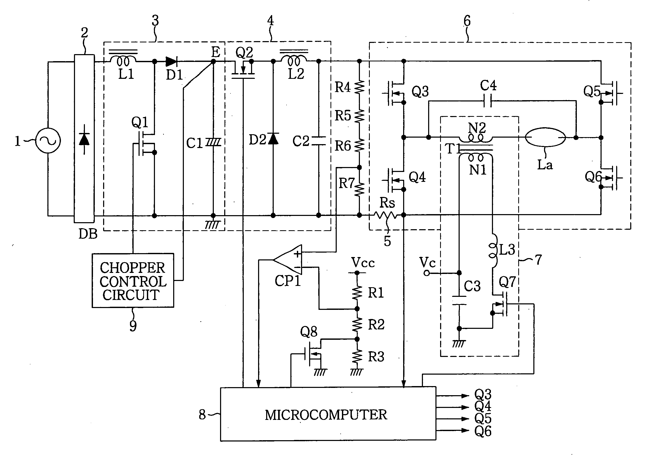
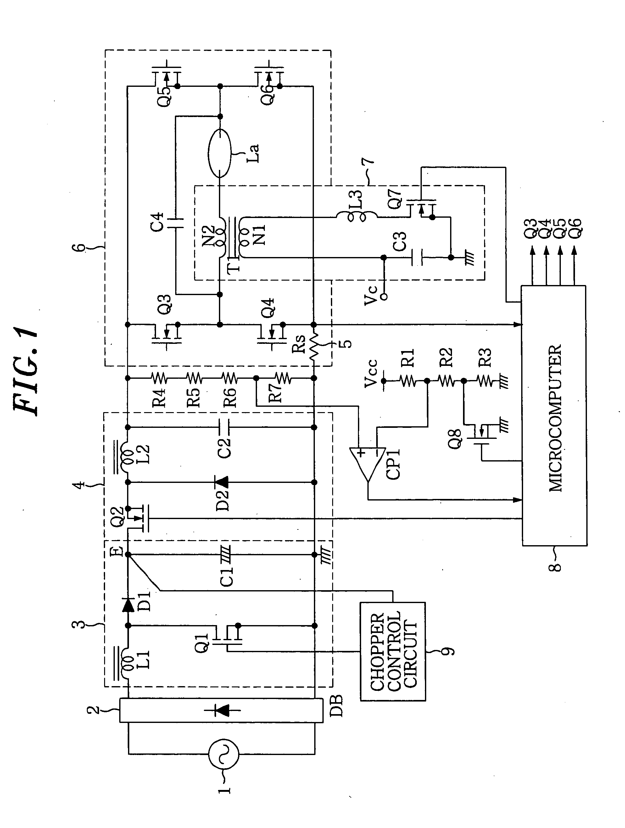
[0046]FIG. 1 is a circuit diagram of a first embodiment of the present invention. Hereinafter, a configuration of the circuit will be described in detail. A DC power source E corresponds to a DC voltage of a smoothing capacitor C1, the voltage being obtained by rectifying and smoothing a commercial AC power source 1, and an output voltage of a step-up chopper circuit 3 connected to an output of a diode bridge DB. However, the DC power source E is not limited thereto, but may be a battery or any of commercial DC power source.

[0047]A rectifier 2 which includes the diode bridge DB full-wave rectifies the commercial AC power source 1 to output a ripple voltage. A series circuit of an inductor L1 and a switching element Q1 is connected to an output end of the diode bridge DB. The smoothing capacitor C1 is connected to both ends of the switching element Q1 via a diode D1. The inductor L1, the switching element Q1, the diode D1, and the smoothing capacitor C1 constitute the step-up chopper...

second embodiment

[0061]FIG. 3 is a circuit diagram of a second embodiment of the present invention. This embodiment further includes, in addition to the configuration of the first embodiment, a comparator CP2 for deciding a power source voltage and voltage-dividing resistors R8 to R11, thereby deciding an input power source voltage VE from the DC power source E to the DC / DC converter 4. The input power source voltage VE is divided by a series circuit of the resistors R8 to R11 and then applied as a detected power source voltage Vb to a non-inverting input terminal of the comparator CP2. A reference voltage Vref is applied to the inverting input terminal of the comparator CP2. If Vb2 becomes an L level, which is then decided as the power interrupt phase. By monitoring an output of the comparator CP2 on a regular basis, the microcomputer 8 switches the ON / OFF of the switching element Q8 such that the output to the inverting input terminal of the comparator CP1 may become Vth4 in the power interrupt ph...

third embodiment

[0064]FIG. 5 is a circuit diagram of a third embodiment of the present invention. In addition to the configuration of the second embodiment, a switching element Sw of a power source bias circuit connected to the power source E is turned ON / OFF by a lighting decision signal from the microcomputer 8, thus reflecting a change in the power source voltage VE on the threshold value for making a decision on the lighting state. When the switching element Sw is ON, a bias current that depends on the DC voltage of the DC power source E is supplied to a connecting point of the resistors R1 and R2 via a series circuit of the resistors R12 and R13, to variably control the threshold value used for making a decision on the lighting state based on the power source voltage. That is, this embodiment can be configured in a manner that the threshold voltage is lowered as the power source voltage decreases. The resistor R1 and R2 may be replaced with a single resistor.

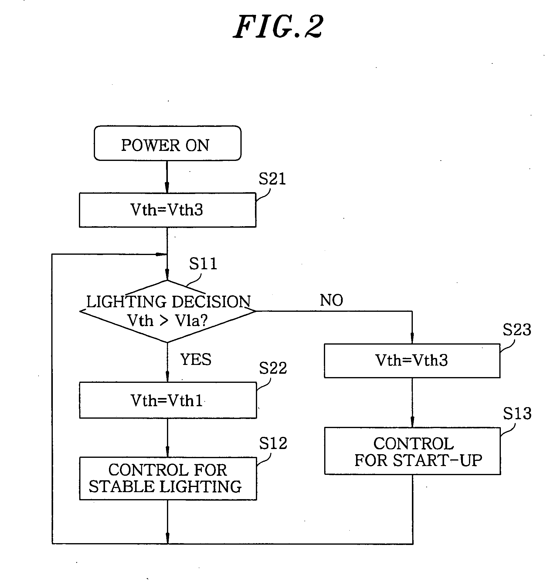
[0065]FIG. 6 is a flow chart for ex...


PUM


Abstract

A high pressure discharge lamp lighting device, includes: a DC/DC converter for converting a power source voltage of a DC power source into a desired DC voltage and stably lighting a high pressure discharge lamp; a DC/AC inverter for inverting the DC voltage into an AC voltage; and a starting pulse generating circuit for generating a high voltage required for the start-up of the high pressure discharge lamp. Further, the high pressure discharge lamp lighting device includes a lighting state decision unit for deciding a lighted/unlighted state of the high pressure discharge lamp; and an operating state switching control unit for switching the operating state of at least one of the DC/DC converter, the DC/AC inverter, and the starting pulse generating circuit to another operating state, depending on a predetermined operation phase out of the start-up, stable lighting and power interrupt phases of the high pressure discharge lamp.

Description

FIELD OF THE INVENTION[0001]The present invention relates to a high pressure discharge lamp lighting device for lighting a high pressure discharge lamp and a luminaire using the same.BACKGROUND OF THE INVENTION[0002]High pressure discharge lamps of compact size provide a high luminous flux, and are analogous to point light sources, and light distribution control thereof is easy. Therefore, they have been widely used as an alternative to incandescent lamps or halogen lamps in recent years.[0003]For lighting this high pressure discharge lamp, there is a discharge lamp lighting device which switches a DC voltage on and off at high frequency and operates the high pressure discharge lamp with a low frequency square wave output via an inductor and a capacitor. When a high frequency power is used to light the high pressure discharge lamp, arc discharge may become unstable because of acoustic resonance, and the lamp may flicker or go out. However, lighting by the low frequency square wave o...

Claims


Application Information

Patent Timeline
IPC IPC(8): H05B41/36
CPCH05B41/288Y02B20/204H05B41/388Y02B20/00
Inventor GORIKI, TAKESHIKAMOI, TAKESHIMATSUZAKI, NOBUTOSHIYAMAHARA, DAISUKE
Owner MATSUSHITA ELECTRIC WORKS LTD
Why Eureka
Try Eureka