Lighting device and luminaire
a technology of light source and light source, which is applied in the direction of lighting apparatus, electroluminescent light sources, light sources, etc., can solve the problems of output electric current deviating from a rated value, the component of the buck converter having a delay time, and the technique cannot improve the electric current variation, etc., to achieve stable lighting up, suppress the variation of light output of these elements, and simple configuration
- Summary
- Abstract
- Description
- Claims
- Application Information
AI Technical Summary
Benefits of technology
Problems solved by technology
Method used
Image
Examples
embodiment 1
[0039]First, a lighting device according to Embodiment 1 of the present invention will be described.
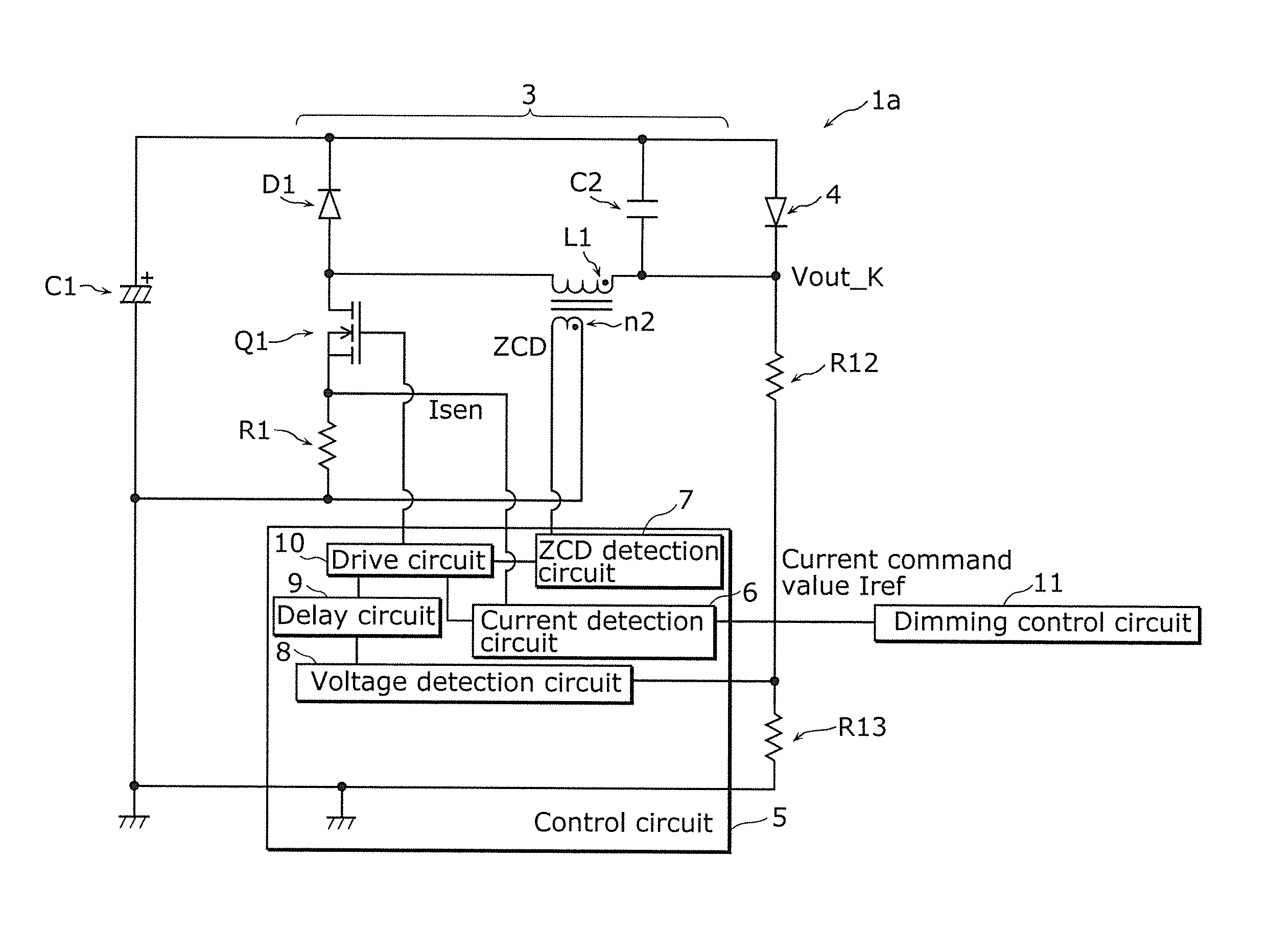
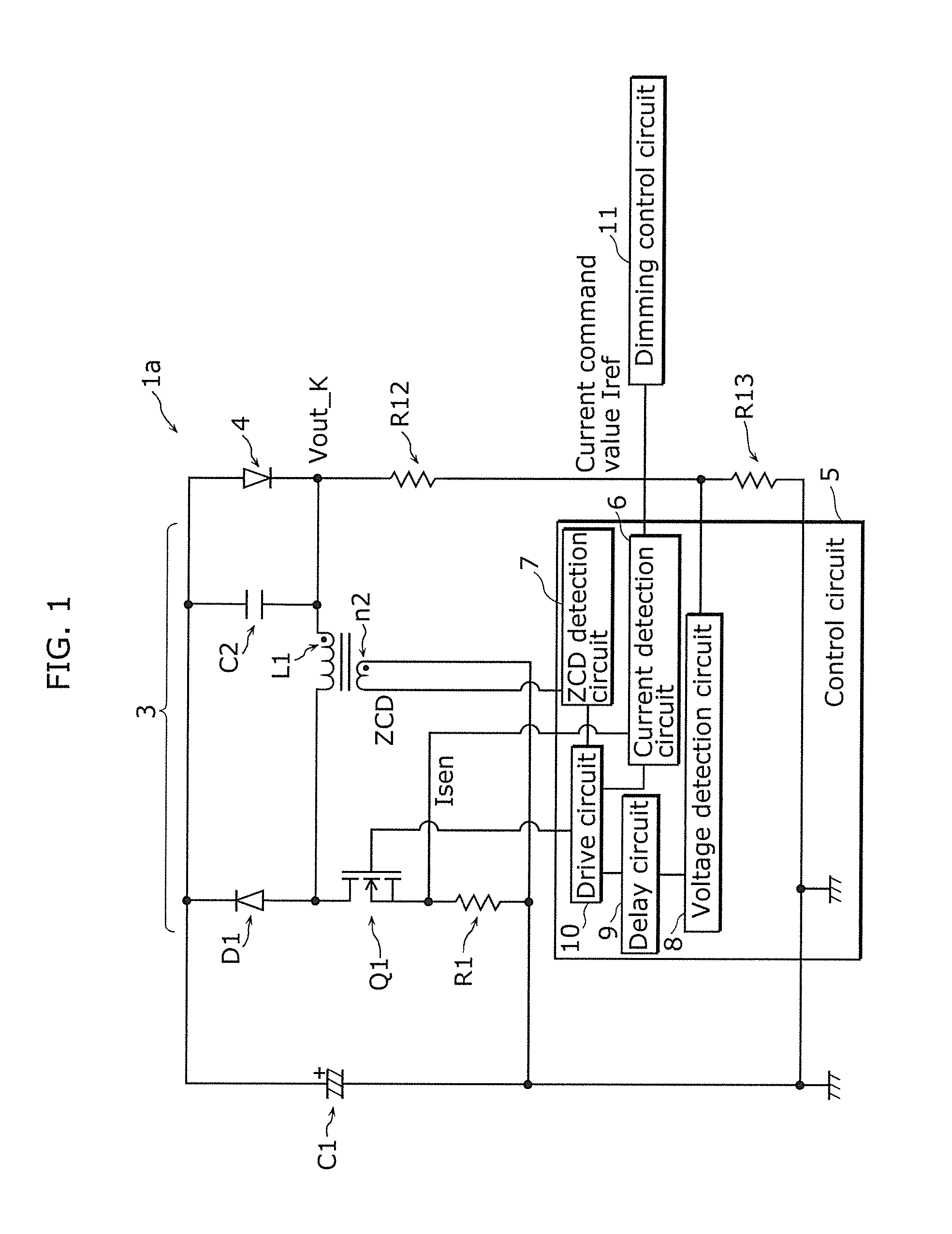
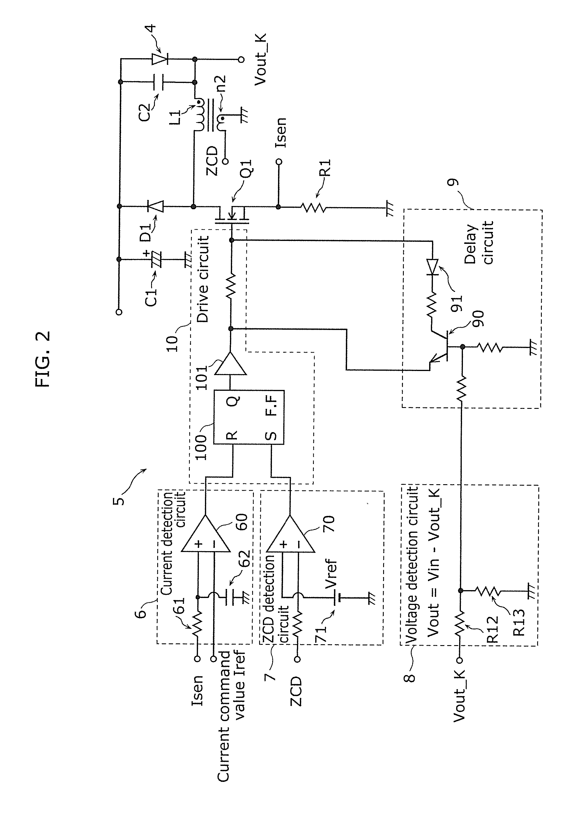
[0040]FIG. 1 is a circuit diagram of a lighting device 1a in Embodiment 1 of the present invention, and FIG. 2 is a detailed circuit diagram of a control circuit 5 included in the lighting device 1a. This technique is different from a background art in that a delay circuit 9 is added in the control circuit 5.
[0041]The lighting device 1a is a device for lighting up an LED 4, which is an example of a solid-state light-emitting element serving as a load, and includes a smoothing capacitor C1 serving as a DC power source, a buck converter 3, the control circuit 5 for controlling the buck converter 3, and a dimming control circuit 11. The buck converter 3 is a constant current output converter that receives an electric current from the smoothing capacitor C1 serving as a DC power source and supplies a predetermined electric current to the LED 4. In other words, this lighting device 1a incl...
embodiment 2
[0086]Next, a lighting device according to Embodiment 2 of the present invention will be described.
[0087]Embodiment 2 is different from Embodiment 1 in the configuration of the buck converter and part of the control circuit. However, the basic operation of the buck converter in Embodiment 2 is similar to that in Embodiment 1. Thus, the following description of Embodiment 2 will be directed only to the difference from Embodiment 1.
[0088]In Embodiment 1, the method of changing the speed of extracting a gate-source electric charge of the switching element Q1 has been discussed as the method for generating the delay time by the delay circuit 9. However, with such a method, there is a possibility that the generated delay time might vary due to component-to-component variations in the threshold voltage, gate capacity and so on of the switching element Q1.
[0089]Accordingly, the present embodiment will illustrate a delay circuit that can generate an accurate delay time with reduced variatio...
embodiment 3
[0101]Next, a lighting device according to Embodiment 3 of the present invention will be described.
[0102]Embodiment 3 is different from Embodiments 1 and 2 in that plural sets of a buck converter, a control circuit and a solid-state light-emitting element (here, an LED) are provided.
[0103]FIG. 10 is a circuit diagram of a lighting device 1c in Embodiment 3. This lighting device 1c includes a plurality of buck converters 3a to 3c for stepping down a DC voltage of the smoothing capacitor C1 serving as a common DC power source and supplying a DC current to LEDs 4a to 4c serving as loads, and a plurality of control circuits 5a to 5c. The present embodiment will be described using a circuit including three buck converters 3a to 3c and three control circuits 5a to 5c.
[0104]Each of the buck converters 3a to 3c has a circuit configuration similar to the buck converter 3 in Embodiment 1. For example, the buck converter 3a includes an inductor L1a, a switching element Q1a, a diode D1a and an...
PUM
 Abstract
Description
Claims
Application Information
 - R&D
- Intellectual Property
- Life Sciences
- Materials
- Tech Scout
- Unparalleled Data Quality
- Higher Quality Content
- 60% Fewer Hallucinations
Browse by: Latest US Patents, China's latest patents, Technical Efficacy Thesaurus, Application Domain, Technology Topic, Popular Technical Reports.
© 2025 PatSnap. All rights reserved.Legal|Privacy policy|Modern Slavery Act Transparency Statement|Sitemap|About US| Contact US: help@patsnap.com


