Optical scanner apparatus

a technology of optical scanners and optical scanners, applied in the direction of optics, optical elements, instruments, etc., can solve the problem that the driving of the mirror cannot be appropriately controlled, and achieve the effect of reducing the variation of the output signal

Active Publication Date: 2016-04-28
MITSUMI ELECTRIC CO LTD
View PDF3 Cites 6 Cited by
  • Summary
  • Abstract
  • Description
  • Claims
  • Application Information

AI Technical Summary

Benefits of technology

[0009]The present invention is made in light of the above problems, and provides an optical scanner apparatus capable of reducing variation of an output signal of a sensor that detects an oscillation angle of a mirror.

Problems solved by technology

In such a case, there is a problem that if light (stray light of laser light or ambient light) is irradiated on the sensor or the sensor interconnect, an output signal of the sensor is varied, and as a result, driving of the mirror cannot be appropriately controlled.

Method used


Image

  • Optical scanner apparatus
  • Optical scanner apparatus
  • Optical scanner apparatus

Examples


first embodiment

Alternative Example of First Embodiment

[0087]In an alternative example of the first embodiment, a cover glass on the package cover in the optical scanner apparatus. Here, in the alternative example of the first embodiment, it is to be noted that, in the explanation of the drawings, the same components as explained above in the first embodiment are given the same reference numerals, and explanations are not repeated.

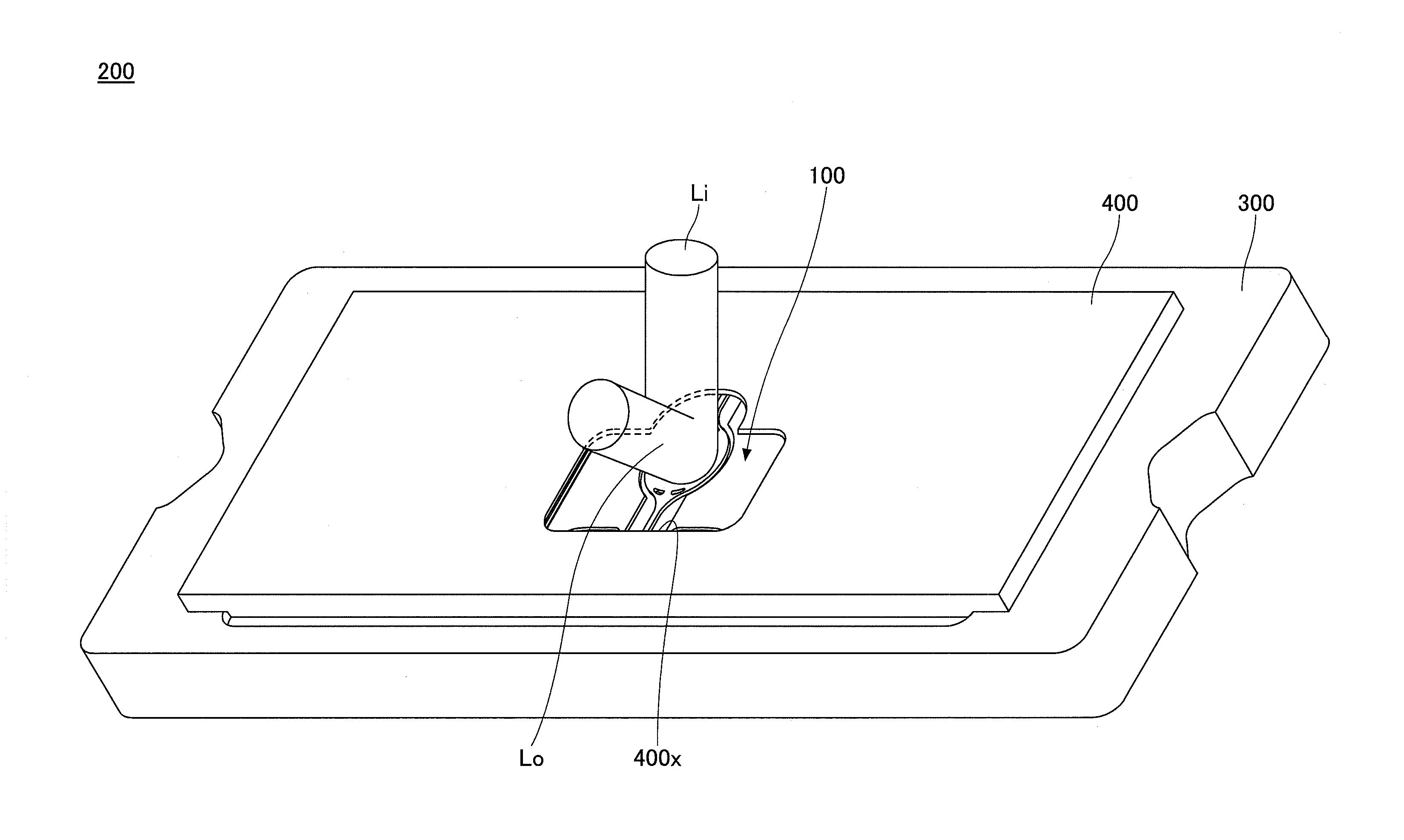
[0088]FIG. 15 is a perspective view illustrating an example of an optical scanner apparatus 200A of an alternative example of the first embodiment. FIG. 16 is a cross-sectional perspective view illustrating an alternative example of the optical scanner apparatus 200A of the first embodiment. As illustrated in FIG. 15 and FIG. 16, the optical scanner apparatus 200A includes the optical scanner unit 100, the ceramic package 300 on which the optical scanner unit 100 is mounted and a package cover 410 that is provided on the ceramic package 300 to cover the optical scanner un...


PUM

PropertyMeasurementUnit
currentaaaaaaaaaa
stressaaaaaaaaaa
resonance frequenciesaaaaaaaaaa

Abstract

An optical scanner apparatus that oscillates a mirror to scan incident light, includes an optical scanner unit that includes a sensor that detects an oscillation angle of the mirror, and an interconnect connected to the sensor; and a shading unit that shades the sensor and the interconnect from stray light of the incident light and ambient light.

Description

CROSS-REFERENCE TO RELATED APPLICATION[0001]The present application is based on and claims the benefit of priority of Japanese Priority Application No. 2014-218994 filed on Oct. 28, 2014, the entire contents of which are hereby incorporated by reference.BACKGROUND OF THE INVENTION[0002]1. Field of the Invention[0003]The present invention relates to an optical scanner apparatus.[0004]2. Description of the Related Art[0005]Conventionally, an optical scanner apparatus is known that includes an optical scanner unit including a mirror, and in which incident light such as laser light or the like is reflected by rotating the mirror around a rotation axis. In this optical scanner apparatus, a sensor is provided that detects an oscillation angle of the mirror under a status that the mirror is driven and oscillated, and inclination of the mirror is detected based on the output signal of the sensor to drive and control the mirror (Patent Documents 1 and 2, for example).[0006]However, there is ...

Claims


Application Information

Patent Timeline
Patent Type & Authority Applications(United States)
IPC IPC(8): G02B26/10G02B26/08
CPCG02B26/0858G02B26/105
Inventor YAMADA, TSUKASASEKINE, HISAMICHIAGA, HISANORITANAKA, TOYOKI
Owner MITSUMI ELECTRIC CO LTD
Why Eureka
Try Eureka