Liquid crystal display panel for curved screen

a technology of liquid crystal display and curved screen, which is applied in non-linear optics, instruments, optics, etc., can solve the problems of distortion and small space for curved screen, and achieve the effect of improving the brightness of curved screen on display and improving the quality of curved screen on image display

Active Publication Date: 2016-04-28
TCL CHINA STAR OPTOELECTRONICS TECH CO LTD
View PDF2 Cites 10 Cited by
  • Summary
  • Abstract
  • Description
  • Claims
  • Application Information

AI Technical Summary

Benefits of technology

[0009]Therefore, an object of the present invention is to solve the main problems of the convention technology by reducing the dark region on the curved screen because of misalignment of the TFT substrate and the CF substrate and improving luminance inequality of images due to the misalignment.
[0020]An object of the present invention is to provide an LCD panel applied to curved screens. The area of the sharing capacitance of each display section is adjusted using a sharing capacitance sheet. So the ratio of the charging voltage on the sub-pixel in the central display to the charging voltage on the primary sub-pixel in the central display section is between the ratio of the charging voltage on the sub-pixel in the first display section to the charging voltage on the primary sub-pixel in the first display section and the ratio of the charging voltage on the sub-pixel in the second display section to the charging voltage on the primary sub-pixel in the second display section. In this way, the brightness of the curved screen on display is improved. The quality of the curved screen on image display is improved as well.

Problems solved by technology

A traditional flat screen needs larger space for a larger display screen, which leads to smaller space for a curved screen.
Because of a RC delay of the scan line, a distortion occurs when the waveform of a normal scan signal is transmitted to the central area of the panel.

Method used


Image

  • Liquid crystal display panel for curved screen
  • Liquid crystal display panel for curved screen
  • Liquid crystal display panel for curved screen

Examples


Embodiment Construction

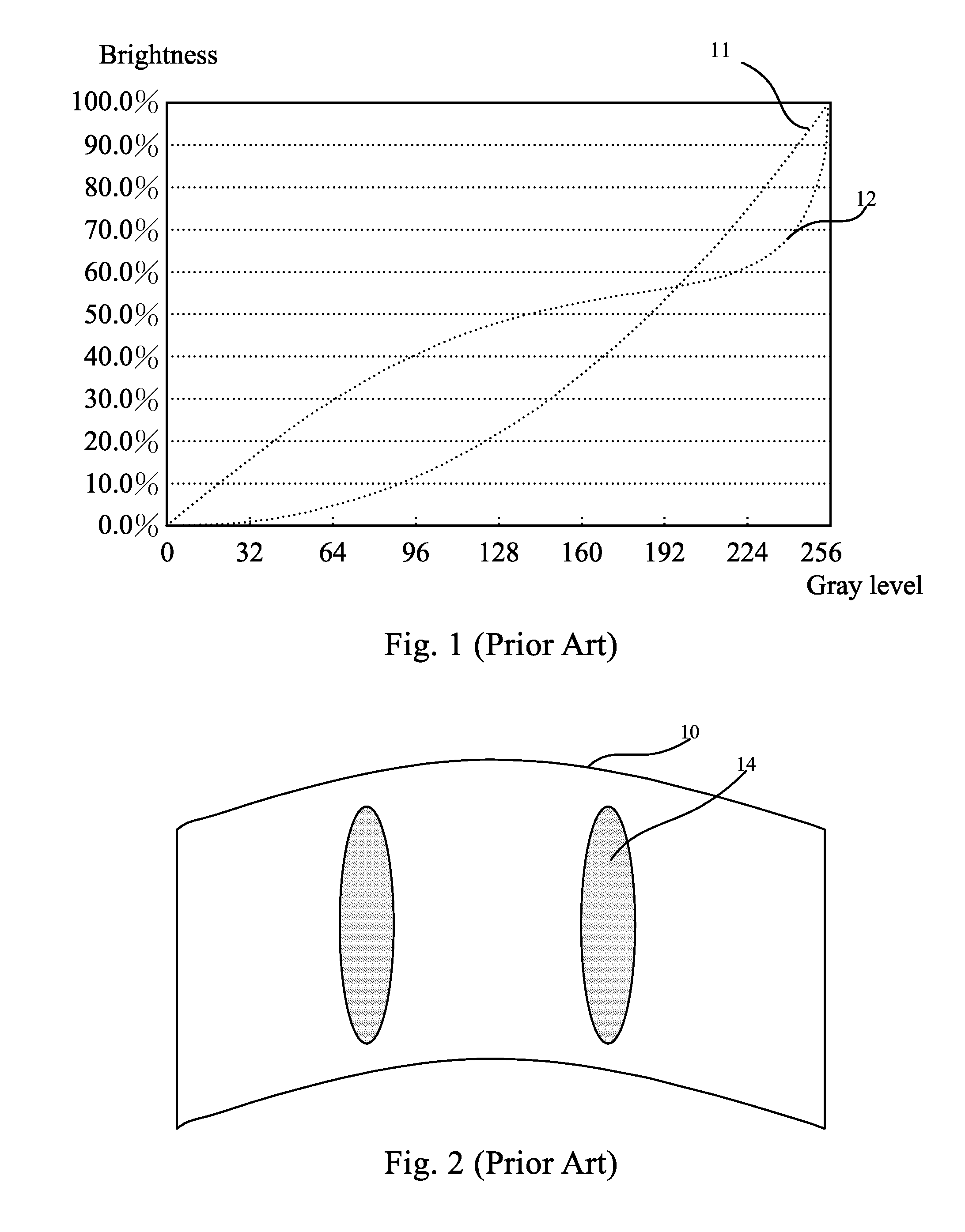
[0030]Spatially relative terms, such as “beneath”, “below”, “lower”, “above”, “upper” and the like, may be used herein for ease of description to describe one element or feature's relationship to another element(s) or feature(s) as illustrated in the figures. It will be understood that the spatially relative terms are intended to encompass different orientations of the device in use or operation in addition to the orientation depicted in the figures. For example, if the device in the figures is turned over, elements described as “below” or “beneath” other elements or features would then be oriented “above” the other elements or features. Thus, the exemplary term “below” can encompass both an orientation of above and below. The device may be otherwise oriented (rotated 90 degrees or at other orientations) and the spatially relative descriptors used herein interpreted accordingly.

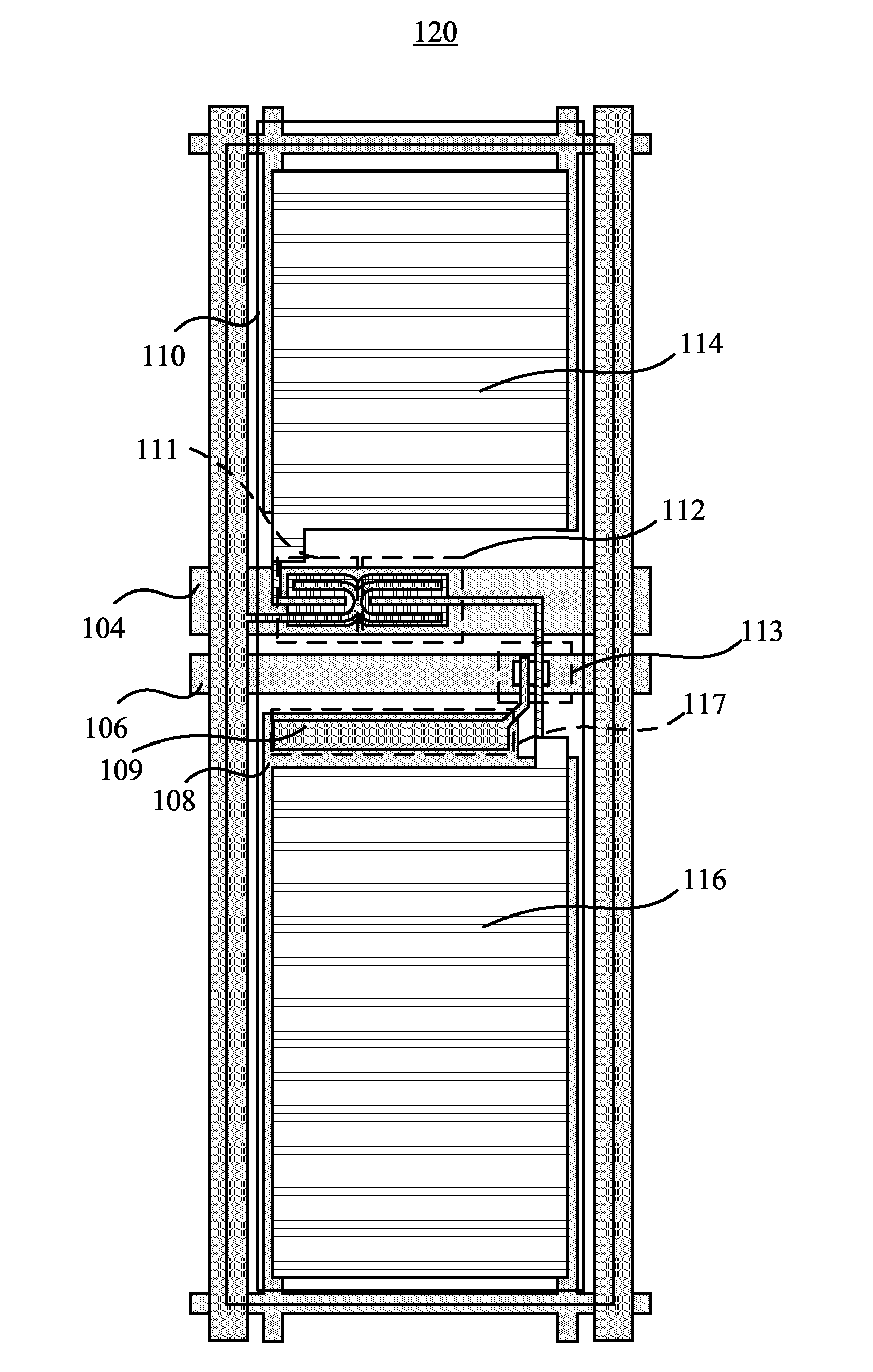
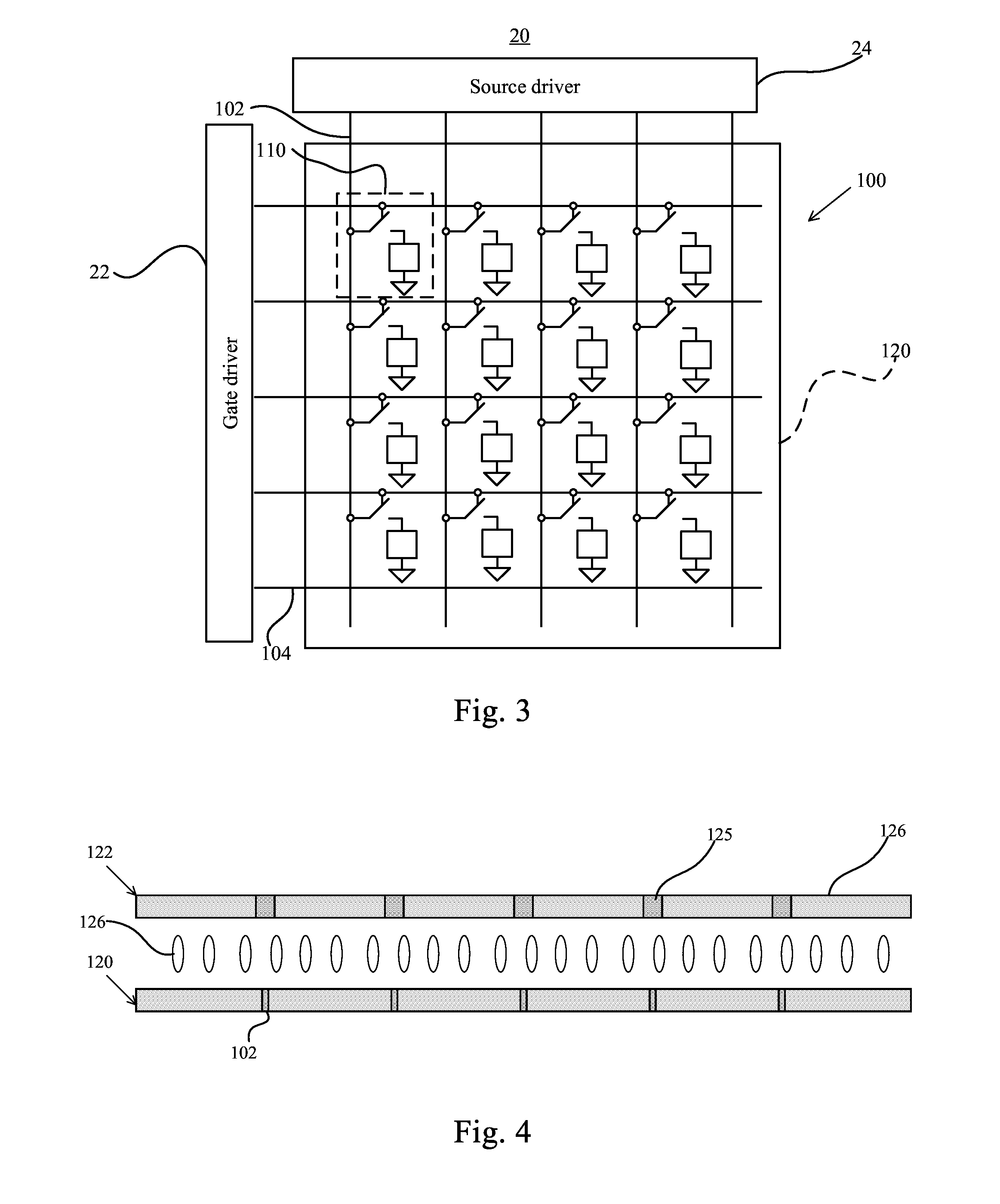
[0031]Please refer to FIG. 3 and FIG. 4. FIG. 3 is a schematic diagram showing an LCD panel 100 used for a...


PUM

PropertyMeasurementUnit
widthaaaaaaaaaa
widthaaaaaaaaaa
charging voltageaaaaaaaaaa

Abstract

An LCD panel applied to a curved screen includes display sections, each of which includes pixel units. Each pixel unit includes a primary sub-pixel, a secondary sub-pixel, a common electrode, and a sharing capacitance sheet. An area of the sharing capacitance of each display section is adjusted using a sharing capacitance sheet. So a ratio of the charging voltage on the secondary sub-pixel to the charging voltage on the primary sub-pixel in the central display section is between the ratio of the charging voltage on the secondary sub-pixel to the charging voltage on the primary sub-pixel in the first display section and the ratio of the charging voltage on the secondary sub-pixel to the charging voltage on the primary sub-pixel in the second display section. Therefore, the brightness of the curved screen on display is improved. The quality of the curved screen on image display is improved as well.

Description

BACKGROUND OF THE INVENTION[0001]1. Field of the Invention[0002]The present invention relates to a liquid crystal display (LCD) panel, and more particularly, to an LCD panel capable of showing good images via a high quality curved screen which is improved by adjusting the area of a sharing capacitance of a pixel in each display section.[0003]2. Description of the Prior Art[0004]The size of display screens becomes larger and larger. A traditional flat screen needs larger space for a larger display screen, which leads to smaller space for a curved screen. Besides, curved screens have the effect of image disclosure so the effect of screen display on the curved screens is better than on traditional flat screens. Consequently, the curved screens apply more and more widely.[0005]However, a thin film transistor liquid crystal display (TFT-LCD) panel used as a curved screen has shortcomings and needs improvement. Please refer to FIG. 1 showing a relationship diagram of the brightness and gr...

Claims


Application Information

Patent Timeline
Patent Type & Authority Applications(United States)
IPC IPC(8): G02F1/1362G02F1/1335G02F1/1343
CPCG02F1/136213G02F2001/134345G02F1/133512G02F1/134309G02F1/13306G02F1/133305G02F1/1362G02F1/134345
Inventor ZHENG, HUA
Owner TCL CHINA STAR OPTOELECTRONICS TECH CO LTD
Why Eureka
Try Eureka