Connector

Active Publication Date: 2016-04-28
IRISO ELECTRONICS CO LTD
View PDF0 Cites 2 Cited by
  • Summary
  • Abstract
  • Description
  • Claims
  • Application Information

AI Technical Summary

Benefits of technology

[0036]For example, the retainer may be formed symmetrically in the height direction of the connector, a lock portion used against the retainer may be provided on the upper portion or the lower portion of each socket terminal, and the socket terminals may be accommodated in an inverted manner in each of the terminal mounting holes provided in two rows in the height direction. With the above, the lock portions, used against the retainer provided in the socket terminals in two rows, may be arranged close to each other and the retainer may

Problems solved by technology

However, in the connector described above, the box-shaped storage portions of the socket terminals are each typically formed by bending a metal piece forming the socket terminal into a complicated box shape, such as a square tube shape or a cylindrical shape; accordingly, a large internal space tha

Method used


Image

  • Connector
  • Connector
  • Connector

Examples


Example

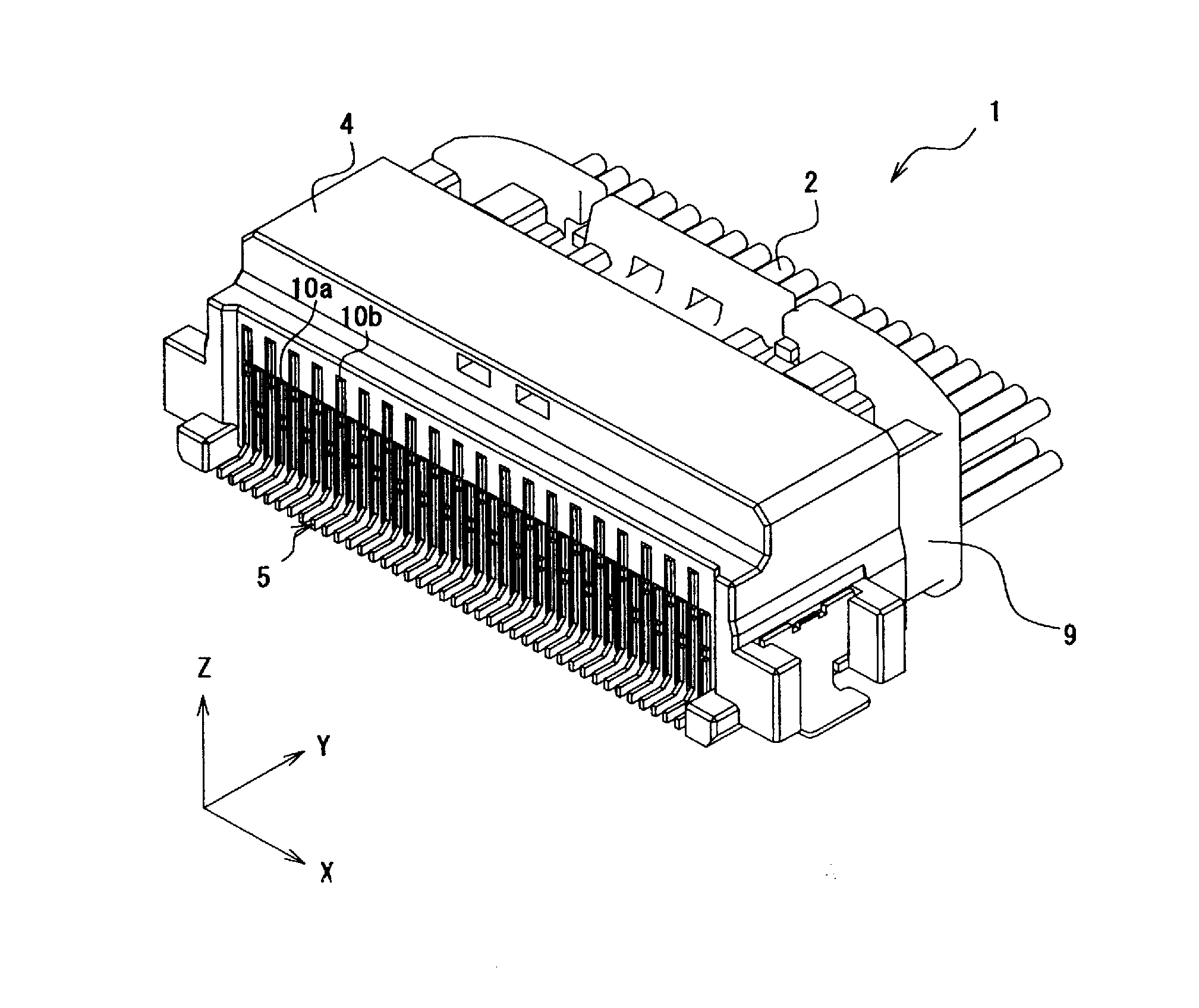
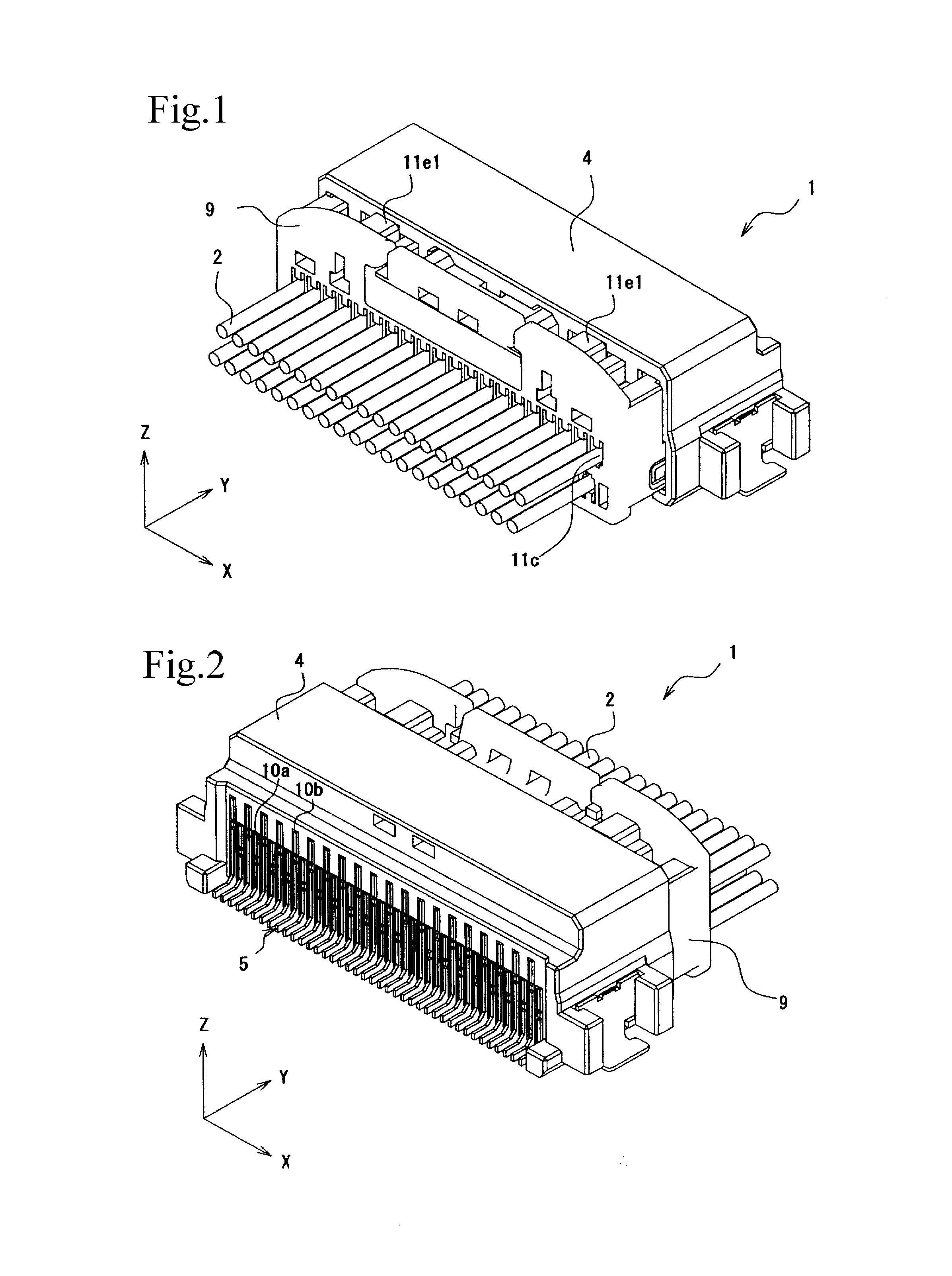
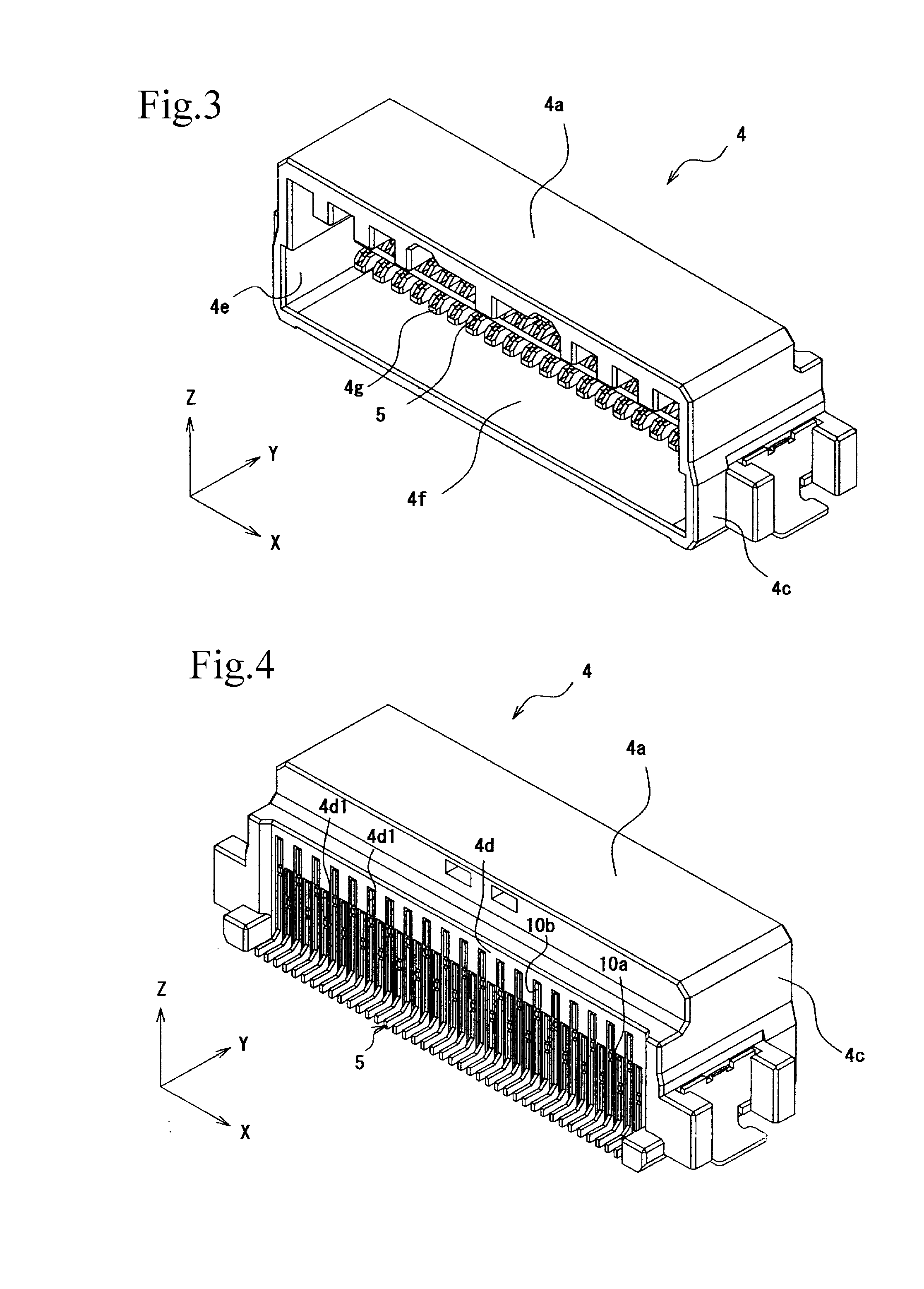
[0072]Hereinafter, an exemplary embodiment of the present disclosure will be described with reference to the drawings.

[0073]In the present description, claims, and drawings, a description will be given while a width direction that extends in a longitudinal direction of a connector 1 illustrated in FIGS. 1 to 34 is an X direction, a front-rear direction that extends in a short direction thereof is a Y direction, and a height direction of the connector 1 is a Z direction, and in the height direction Z, a top surface side of the connector 1 is an “upper side” and the bottom surface side of the connector 1 is a “lower side”. Note that the up-down direction, the left-right direction, and the front-rear direction in the description do not limit the direction in which the connector of the present disclosure is used. Furthermore, since a right side view and a left side view of a plug terminal 5 will be illustrated in a bilaterally symmetrical manner, the left side view is omitted.

Exemplary ...


PUM


Abstract

Socket terminals include flat bar-like connection pieces that are in conductive contact with plug terminals, and the plug terminals include fork-shaped terminal portions that are in conductive contact with the socket terminals through the flat bar-like connection pieces. Plate surfaces of the plug terminals extend in a height direction and are fixed to a plug housing. Furthermore, fork-shaped terminal portions include contact recesses having openings in plate edges on a socket terminal insertion side. Contact projections of the contact recesses hold the flat bar-like connection pieces of the socket terminals that have been inserted through the openings in between in a direction (an up-down direction) that extends along the plate surfaces of the plug terminals.

Description

BACKGROUND OF THE INVENTION[0001]1. Field of the Invention[0002]The present disclosure relates to a connector including a plug connector and a socket connector.[0003]2. Description of the Related Art[0004]In electric devices, a connector that includes a plug connector that is fixed to a circuit board and a socket connector that is fixed to a conductor is used as a connector that electrically connects a conductor, such as an electric wire, and a circuit board. In such a connector, typically, pin-shaped plug terminals are provided in the plug connector, and socket terminals that are in conductive contact with the plug terminals are provided in the socket connector (as an example of the same type of connector, Japanese Unexamined Patent Application Publication No. 2007-134217). The above socket terminals are each provided with a box-shaped storage portion in which the pin-shaped plug terminal is inserted and retained, and the socket terminals described above accommodate the pin-shaped ...

Claims


Application Information

Patent Timeline
IPC IPC(8): H01R12/51H01R13/11
CPCH01R13/112H01R12/51H01R12/716H01R12/724H01R13/04H01R13/41
Inventor SAKAMOTO, TETSUMA
Owner IRISO ELECTRONICS CO LTD
Why Eureka
Try Eureka