Vehicle wiper

a wiper and vehicle technology, applied in the field of vehicle wipers, can solve the problems of affecting the styling of the car, complicated back face side of the arm head, and difficult to form long grooves, and achieve the effect of suppressing the tensile for

Active Publication Date: 2016-05-05
DENSO CORP
View PDF9 Cites 16 Cited by
  • Summary
  • Abstract
  • Description
  • Claims
  • Application Information

AI Technical Summary

Benefits of technology

[0059]According to the above configuration, due to providing the defrosting heater to the second nozzle member, freezing of washer fluid or the like in the vicinity of the ejection port of the nozzle member can be thawed. The conductor wire is also a heater conductor wire connected to the heater, and so a large tensile force can be suppressed from acting while a slack is prevented in the heater conductor wire.

Problems solved by technology

However, a vehicle wiper is a design component disposed on the vehicle exterior, and there is some concern that a cutaway portion in the retainer for projecting the nozzle member might be detrimental to styling the vehicle wiper, and hence might be detrimental to styling of the car (Issue 1).
However, the back face side of the arm head is complicated in such vehicle wipers, and, in particular, it is difficult to form long grooves when there is a desire to lay out two hoses (Issue 2).
However, in cases in which an urging spring is employed in place of the above tension spring, there is a tendency for the oriented position of the urging spring with respect to the retainer to change greatly when the retainer swings with respect to the arm head.
There is accordingly a concern of the urging spring hitting the cover, and not being able to maintain a good attachment state of the cover (Issue 3).
However, in such cases there is a need to form a hole or the like at the wall of the retainer for the engagement hook to engage with.
This may be detrimental to the appearance of the vehicle wiper (Issue 4).
However, in a configuration such as in the above vehicle wiper in which a conductor wire is laid out along a hose, there is a concern that a large tensile force may act on the conductor wire at the position corresponding to the moveable coupling portion of the wiper arm, and may cause a line break.
In such a situation, the hose is readily extended, however the conductor wire does not readily extend, and so there is a concern for line breakages.
However, in such cases, a longer conductor wire is required, a space is necessary in which the slack portion of the conductor wire can move freely, and the slack portion of the conductor wire provides the detrimental effect on the aesthetics (Issue 5).

Method used


Image

  • Vehicle wiper
  • Vehicle wiper
  • Vehicle wiper

Examples


Embodiment Construction

[0094]Explanation follows of a first exemplary embodiment of a vehicle wiper, with reference to FIG. 1 to FIG. 11.

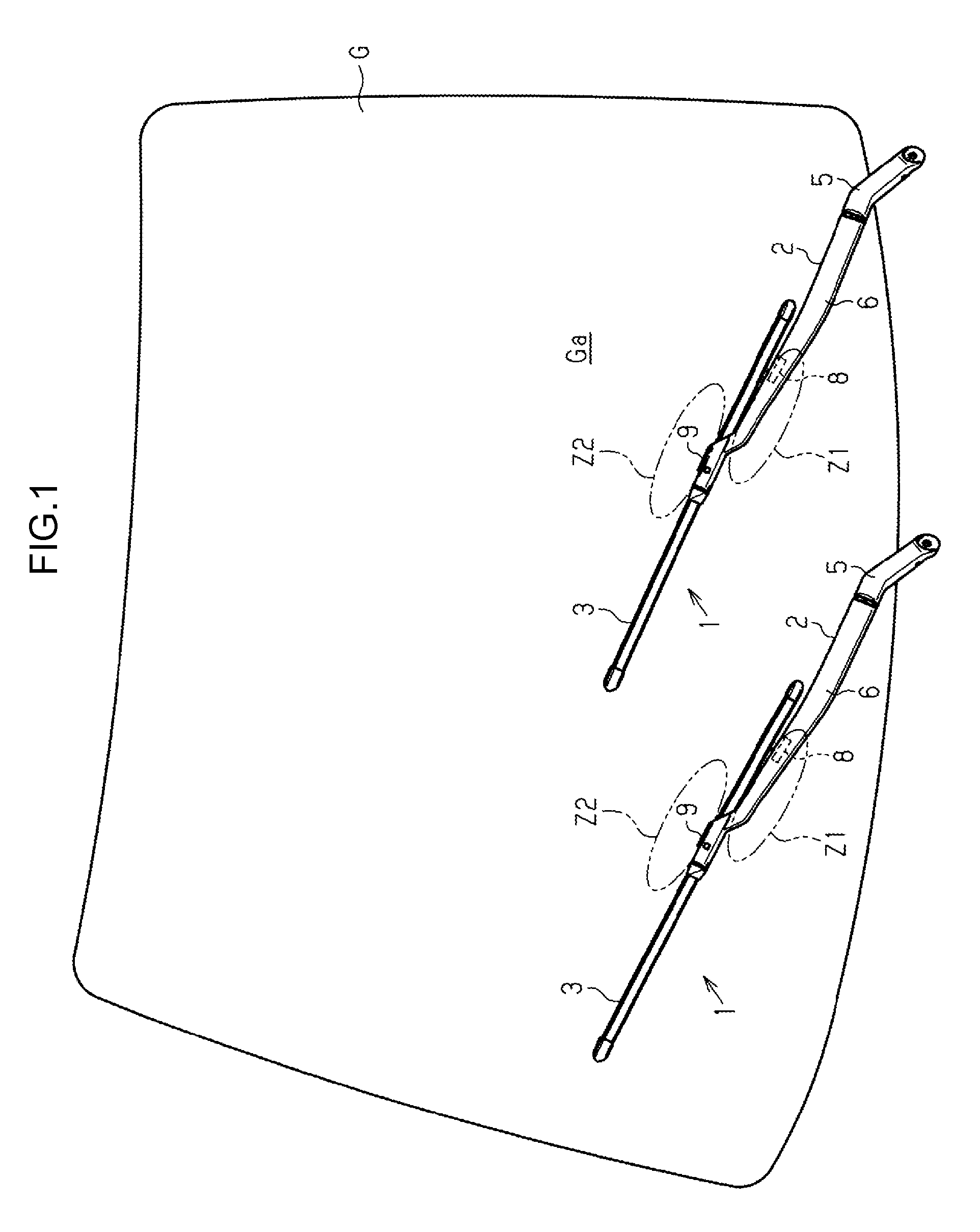
[0095]As illustrated in FIG. 1, vehicle wipers 1 are respectively provided on a driver seat side (right side in FIG. 1) and on the passenger seat side (the left side in FIG. 1) for wiping a wiping surface Ga of a vehicle windshield glass G on the vehicle cabin outside.

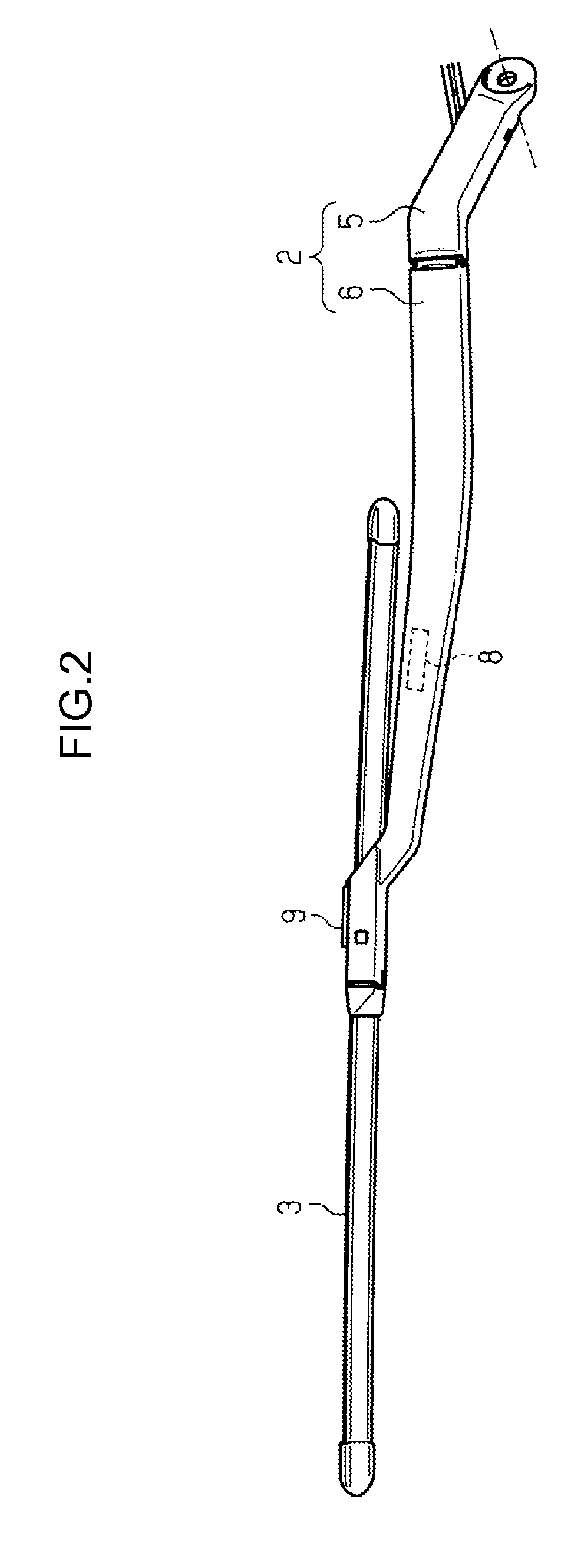
[0096]As illustrated in FIG. 1 and FIG. 2, each of the vehicle wipers 1 is equipped with a wiper arm 2, and a wiper blade 3 coupled to the wiper arm 2.

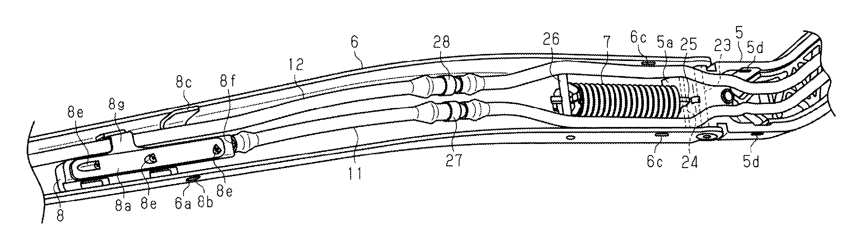
[0097]The wiper arm 2 is fixed to a pivot shaft (not illustrated in the drawings) that is swung to-and-fro by driving force of a non-illustrated motor, that is a forward / reverse rotation controlled motor, and is equipped with an elongated shaped arm head 5 that swings integrally with the pivot shaft. An elongated shaped retainer 6 is coupled to the length direction leading end portion of the arm head 5 so as to be capable of swinging with respect to the pivot...


PUM


Abstract

A vehicle wiper comprises a retainer that is formed in an elongated shape open at the lower side facing toward a windshield, and that is provided so as to be capable of swinging about a shaft axis of a pivot shaft that is swung to-and-fro; a first nozzle member that is housed inside the retainer, and that is capable of ejecting washer fluid from an ejection portion; and 1 a retainer cover member that closes off an opening of the retainer, and that is formed with a window through which the ejection portion of the first nozzle member is externally exposed.

Description

CROSS-REFERENCE TO RELATED APPLICATIONS[0001]This application claims priority under 35 USC 119 from Japanese Patent Application No. 2014-225407 filed on Nov. 5, 2014, Japanese Patent Application No. 2014-230983 filed on Nov. 13, 2014, Japanese Patent Application No. 2015-46175 filed on Mar. 9, 2015, Japanese Patent Application No. 2015-53566 filed on Mar. 17, 2015, and Japanese Patent Applications No. 2015-134082 and No. 2015-134084 filed on Jul. 3, 2015, the disclosures of which are incorporated by reference herein.BACKGROUND OF THE INVENTION[0002]1. Technical Field[0003]The present invention relates to a vehicle wiper.[0004]2. Related Art[0005]Hitherto, there have been wiper arms of vehicle wipers that include an arm head and a retainer, with, for example, retainers having a cross-section orthogonal to the length direction formed in a substantially angular-U shape open on the lower side facing toward the wiping surface, with the opening of the retainer closed off with a cover (see...

Claims


Application Information

Patent Timeline
Patent Type & Authority Applications(United States)
IPC IPC(8): B60S1/52B60S1/02B60S1/34B60S1/40
CPCB60S1/522B60S1/3429B60S1/023B60S1/4006B60S1/3413B60S1/3415B60S1/3468B60S1/3481B60S1/3484B60S1/3805
Inventor UCHIYAMA, KEITAUCHINO, YOSHIYUKIHIRAO, KOUICHIYOSHIMOTO, TAKAOSHIMIZU, AKIO
Owner DENSO CORP
Why Eureka
Try Eureka