
Belt conveyor device for the suspended transport in particular, by means of vacuum, of goods to be conveyed

a belt conveyor and suspended transport technology, applied in the direction of conveyors, rollers, conveyor parts, etc., can solve the problems of high degree of wear, unsatisfactory seal between the belt and the component to be conveyed, and high price of the conveyor belt for vacuum belt conveyor devices

Inactive Publication Date: 2002-07-23
NSM MAGNETTECHN
View PDF11 Cites 17 Cited by
  • Summary
  • Abstract
  • Description
  • Claims
  • Application Information

AI Technical Summary

Benefits of technology

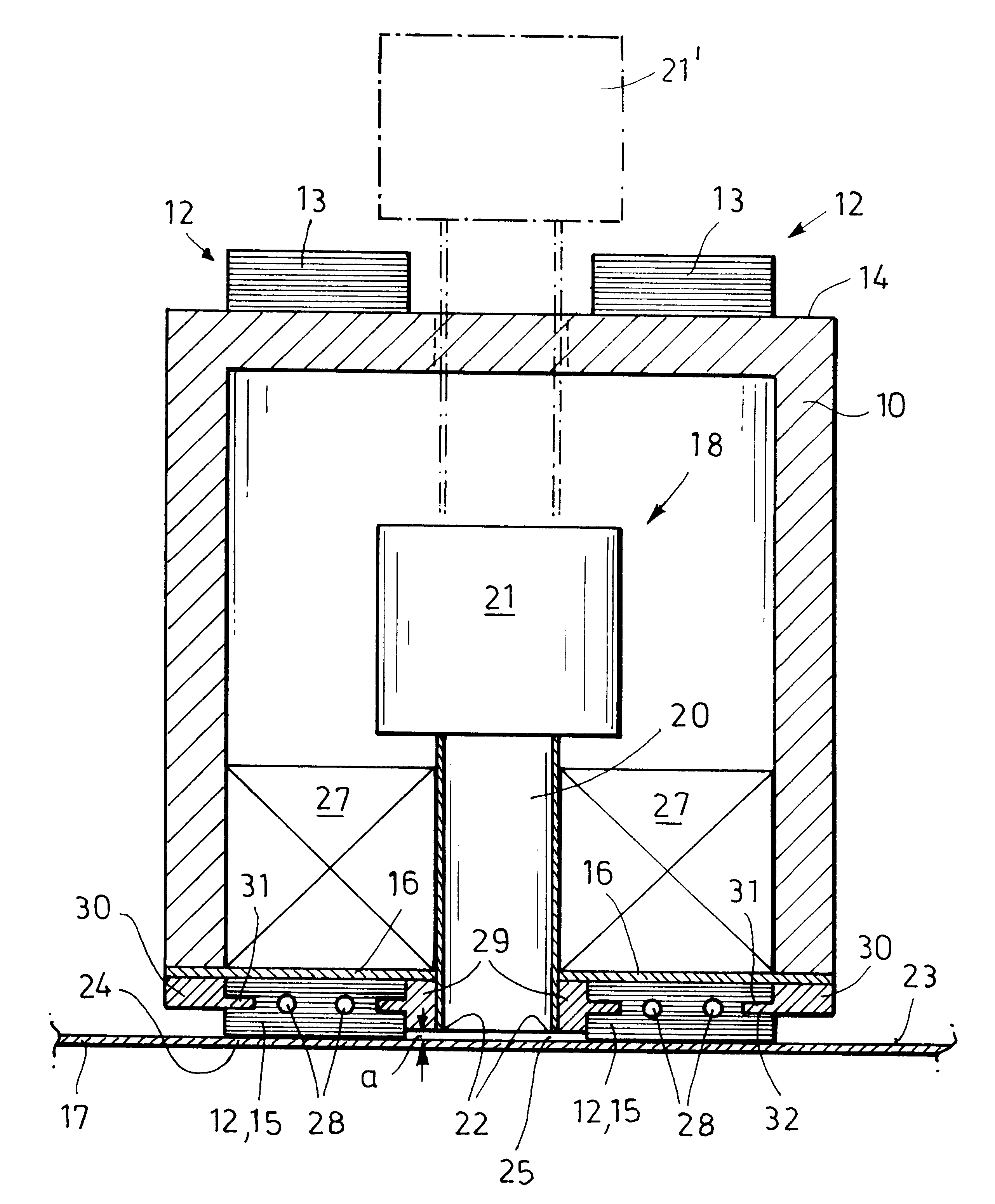
The vacuum generators for at least one part of the suction nozzles are preferably connectable and disconnectable individually and / or in groups. It is thereby possible deliberately to interrupt the generation of the vacuum at selected suction nozzles and thus to release the transported components exactly at a desired location by turning off the vacuum for a short time.
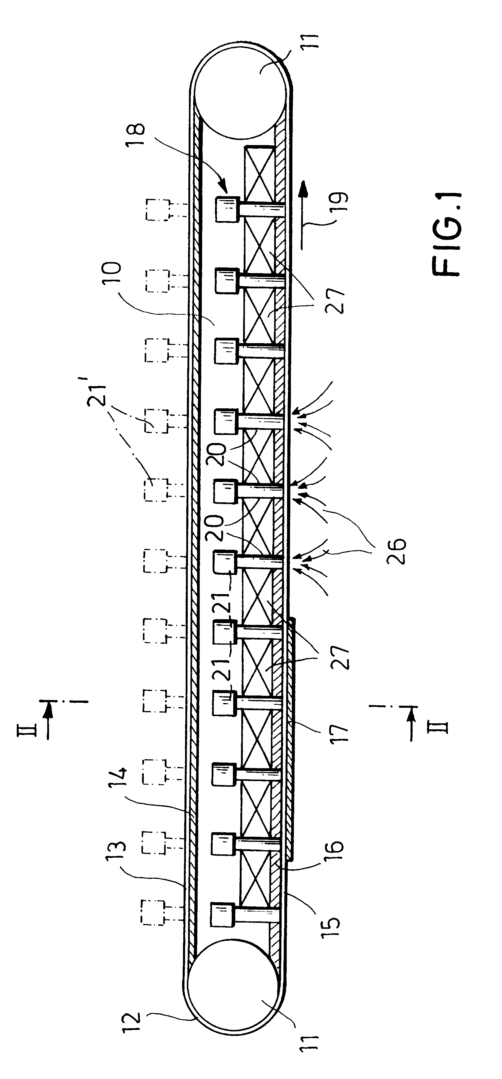
The vacuum generators are advantageously disposed in the vicinity of the nozzle edges of the suction nozzles, which results in a particularly compact form of construction and whereby losses due to suction lines which are too long can be avoided. The suction nozzles can be disposed at a constant, fixed spacing from each other on the holding track of the belt conveyor device. It is particularly advantageous, however, if the suction nozzles are disposed on the holding track so that their spacing from each other is adjustable, especially if the number of suction nozzles which are provided on the holding track of the conveyor is variable. The spacings of the suction nozzles and the number thereof can then be adjusted in the optimum manner, depending on the size and weight of the components to be conveyed, so that for each component to be conveyed a sufficient number of nozzles always simultaneously generates the vacuum at the upper surface thereof and thereby hold the component, but so that no more suction nozzles have to be used than are necessary. It is also possible, of course, to achieve a corresponding effect with an arrangement of the suction nozzles at a fixed spacing from each other, for example if the components to be conveyed are particularly light, by arranging for only each second or even for only each third nozzle to be effective and to generate suction at the upper surface of the goods to be conveyed, with the remaining nozzles only being effective during the transport of heavier components.
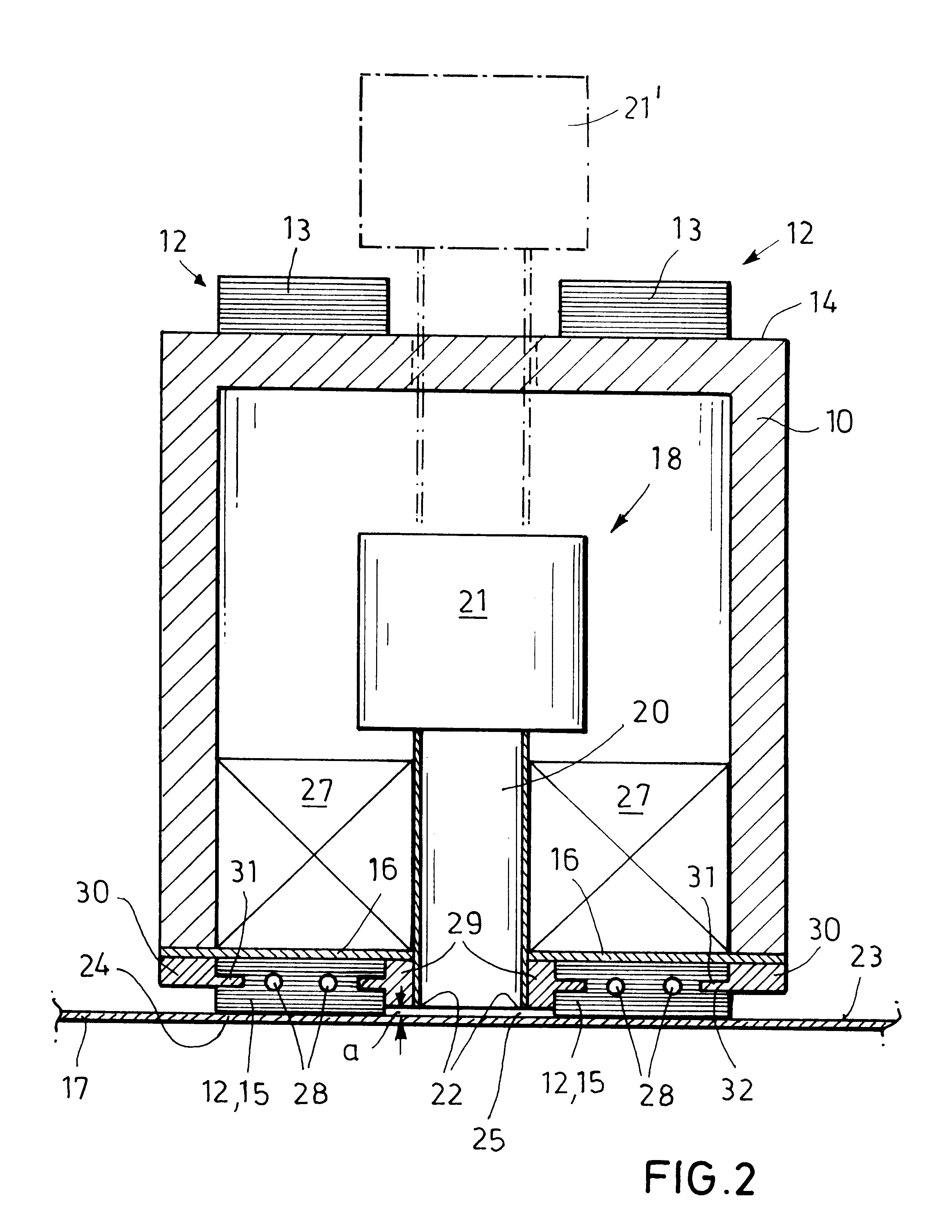
If the conveyor belt or conveyor belts are reinforced with steel inserts, not only do they have a particularly long service life, but the belts themselves--provided that the conveyor is provided with magnet units--are pulled strongly by the magnets against the underside of the conveyor and are seated against the latter in a substantially air-tight manner, so that in this region also the vacuum device cannot suck in secondary air. The conveyor belt or conveyor belts are advantageously pressed against the holding track by means of retaining strips which act on their longitudinal sides, in order reliably to prevent sagging of the belts if the latter are not provided with steel inserts and / or if the conveyors are not provided with magnet units.

Problems solved by technology

Due to their special form of construction, conveyor belts for vacuum belt conveyor devices are very expensive.
Moreover, they are also subject to a high degree of wear, because the individual suction devices which protrude from a belt are frequently damaged or torn off completely, and then have to be laboriously repaired or replaced.
In vacuum conveyor belts such as these, however, the seal between the belt and component to be conveyed is often unsatisfactory, so that unusually powerful vacuum devices have to be used in order to hold the components to be conveyed securely on the conveyor.
This results in a particularly compact, low-maintenance form of construction.

Method used


Image

  • Belt conveyor device for the suspended transport in particular, by means of vacuum, of goods to be conveyed
  • Belt conveyor device for the suspended transport in particular, by means of vacuum, of goods to be conveyed
  • Belt conveyor device for the suspended transport in particular, by means of vacuum, of goods to be conveyed

Examples


Embodiment Construction

The belt conveyor device which is illustrated in a considerably simplified form in the drawings comprises a box-like supporting construction 10, at the front and rear ends of which deflection rollers 11 for two conveyor belts 12 are disposed. The arrangement is designed so that the empty belt runs 13 of the conveyor belts, which travel on the upper surface of the supporting box 10, travel on the flat surface 14 of the supporting box, whilst the loaded belt runs 15 of the belts 12 are seated at the bottom of the supporting construction 10 against a holding track 16 which is provided there.

So as to be able to transport goods to be conveyed, particularly metal sheets 17 or other plate-like components, in a suspended manner by means of the belt conveyor device, the conveyor device is provided with a vacuum device which is denoted in its entirety by 18, by means of which the metal sheets 17 to be conveyed are held by suction against the two conveyor belts 12.

The vacuum device 18 essentia...


PUM


Abstract

A band conveyor device used for the suspended transport of plate-like workpieces, metal sheets or the like and has a conveyor belt which is moved along a holding track. A vacuum device holds the goods to be conveyed by suction against a transport side of the conveyor belt. The vacuum device has a multiplicity of suction nozzles which are disposed on the holding track at the transport side of the conveyor belt, so that their nozzle edges which point towards the transported goods to be conveyed are situated at a short distance from the goods. The air necessary for holding the goods is drawn through local, separate invariable vacuum zones, through which the goods pass in succession along the transport path.

Description

This invention relates to a belt conveyor device for the suspended transport in particular, by means of vacuum, of goods to be conveyed, particularly plate-like workpieces, metal sheets or the like, comprising at least one conveyor belt which can be moved along a holding track and comprising a vacuum device which holds the goods to be conveyed, by suction, against a transport side of the at least one conveyor belt.BACKGROUND OF INVENTIONVacuum belt conveyors of this type are frequently used in the sheet metal processing industry, in areas where metal sheets or workpieces made of sheet metal, such as can lids, panels in the automobile industry or the like, have to be conveyed suspended from one processing station to a further processing location. Vacuum belt conveyors are used in particular for the transport of non-ferromagnetic materials, for example for aluminum sheets, plastics sheets or wooden materials. The transported goods to be conveyed are held by suction, by the vacuum devi...

Claims


Application Information

Patent Timeline
IPC IPC(8): B65G21/20
CPCB65G21/2036
Inventor ULRICH, HANS ANTON
Owner NSM MAGNETTECHN
Learn More