Air brake hose support bracket

a technology for air brake hoses and support brackets, which is applied in the direction of machine supports, brake systems, manufacturing tools, etc., can solve the problems of inconvenience and possible safety concerns, and achieve the effect of increasing the rotational range and facilitating the attachment of the rail car air brake hose assembly

Active Publication Date: 2016-05-05
IRECO INC
View PDF1 Cites 14 Cited by
  • Summary
  • Abstract
  • Description
  • Claims
  • Application Information

AI Technical Summary

Benefits of technology

[0009]In achieving these types of functions of air brake hose support brackets, the present disclosure seeks to address an objective of having a very durable and securely mountable support bracket that still affords an important advantage of attachment to the coupler casting itself rather than to railway car bodies and / or frames and / or yokes, particularly important for railway cars having a so-called cushioning feature whereby the coupler and its yoke are allowed to move horizontally “into” the railway car in response to generally longitudinal forces experienced during operation, including coupling, braking, and negotiating curves. The present disclosure exhibits various advantages over prior structures including bracket units that mount to the coupler. These advantages, discussed in more detail hereinafter, include: easier, faster and more secure installation; greatly reducing susceptibility to damage due to bypassing couplers of adjoining railcars; avoidance of contact with the striker when the coupler is in the “buff” position (pushed all the way in toward the striker); enhanced universality by fitting on a variety of different coupler styles of different manufacturers; more secure attachment to the coupler; and avoidance of interference with other functions required of couplers.
[0013]In a further aspect of this disclosure, a railway car air brake hose support bracket of the present disclosure is adapted to suspend a railway air brake hose assembly from an upper compartment of an uncoupling mechanism housing of a railway car coupler, the air brake hose support bracket having a first attachment member and a second attachment member oriented with respect to each other such that, whether connected to each other by a member that directly or indirectly joins same, present a wrap-around effect with respect to the coupler. The first attachment member connects to a coupler housing beneath a railway car coupler head, and the second attachment member connects to an air brake hose support lug of the railway car coupler, the first attachment member and the second attachment member being laterally spaced from each other. The bracket further includes a lower portion that has an underside and a grasping feature inward of the railway car with respect to the coupler along with an air hose connector that is adapted and structured to engage with an air brake hose assembly while allowing rotation of the air hose connector, the grasping feature securely engaging the air hose connector to the lower portion, with at least part of the air hose connector being below the underside of the lower portion, with the result that the air brake hose support bracket suspends the air brake hose assembly from the railway car coupler. The range of rotation of the air hose connector can be restricted by stop member or members. In alternate arrangement, the air hose connector is movable (such as generally vertically) to avoid contact with the stop member or members, thereby increasing the range of rotational motion in order to facilitate attachment of the railway air brake hose assembly to the air hose connector. In one embodiment, the rotational motion is achieved by mounting the air hose connector to a single shaft; in another embodiment, a pair of shafts is utilized for this purpose, typically being guided by a slot pair.

Problems solved by technology

It will be appreciated that uncoupling of air brake hose assemblies along a railway train while in transport mode typically will cause emergency braking and perhaps excessively abrupt stopping of the train cars involved, which can lead to inconvenience and possible safety concerns.
Damage to equipment and even derailment can be included in these concerns.

Method used


Image

  • Air brake hose support bracket
  • Air brake hose support bracket
  • Air brake hose support bracket

Examples


Embodiment Construction

[0061]As required, detailed embodiments of the present invention are disclosed herein; however, it is to be understood that the disclosed embodiments are merely exemplary of the invention, which may be embodied in various forms. Therefore, specific details disclosed herein are not to be interpreted as limiting, but merely as a basis for the claims and as a representative basis for teaching one skilled in the art to variously employ the present invention in virtually any appropriate manner.

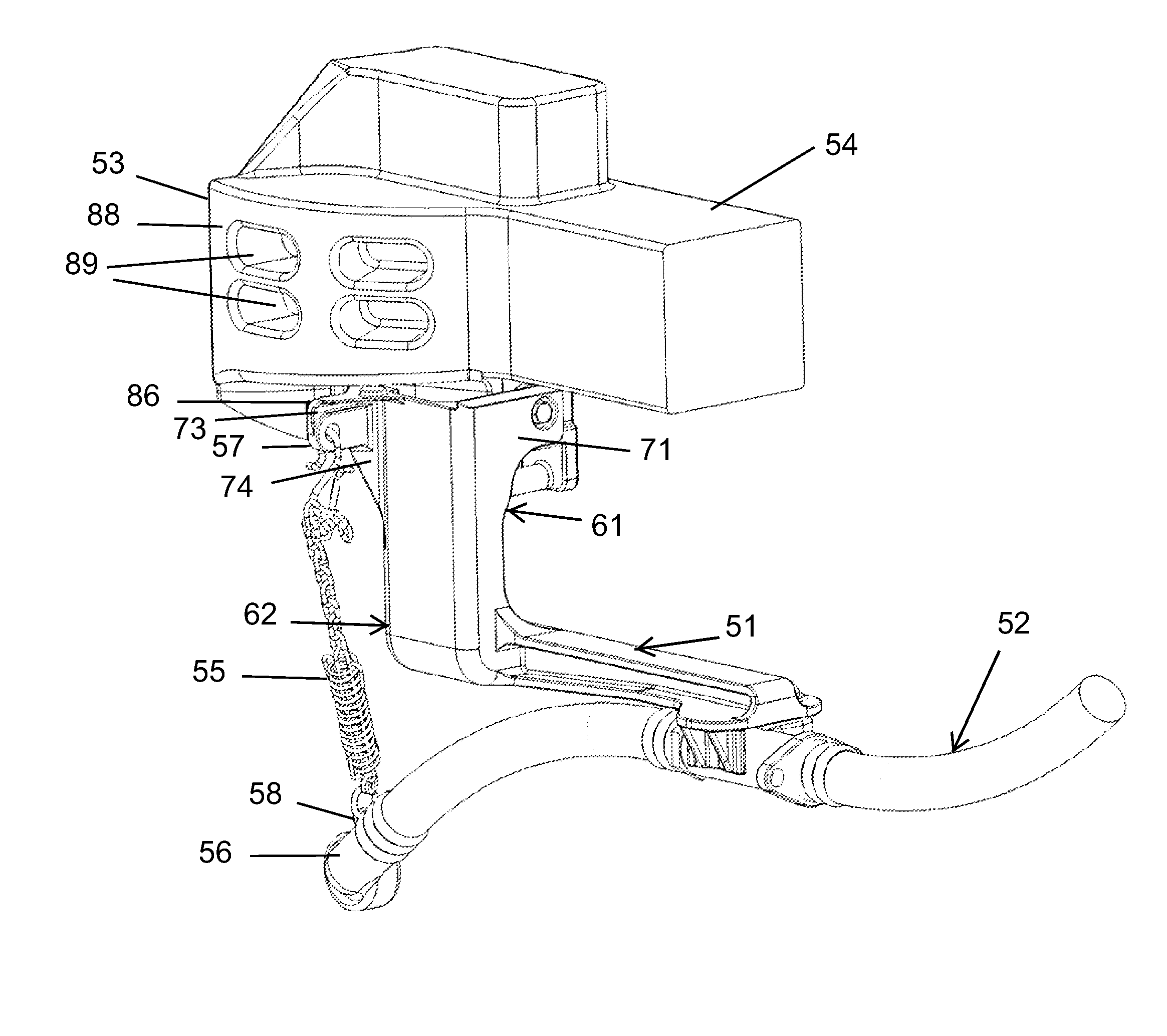
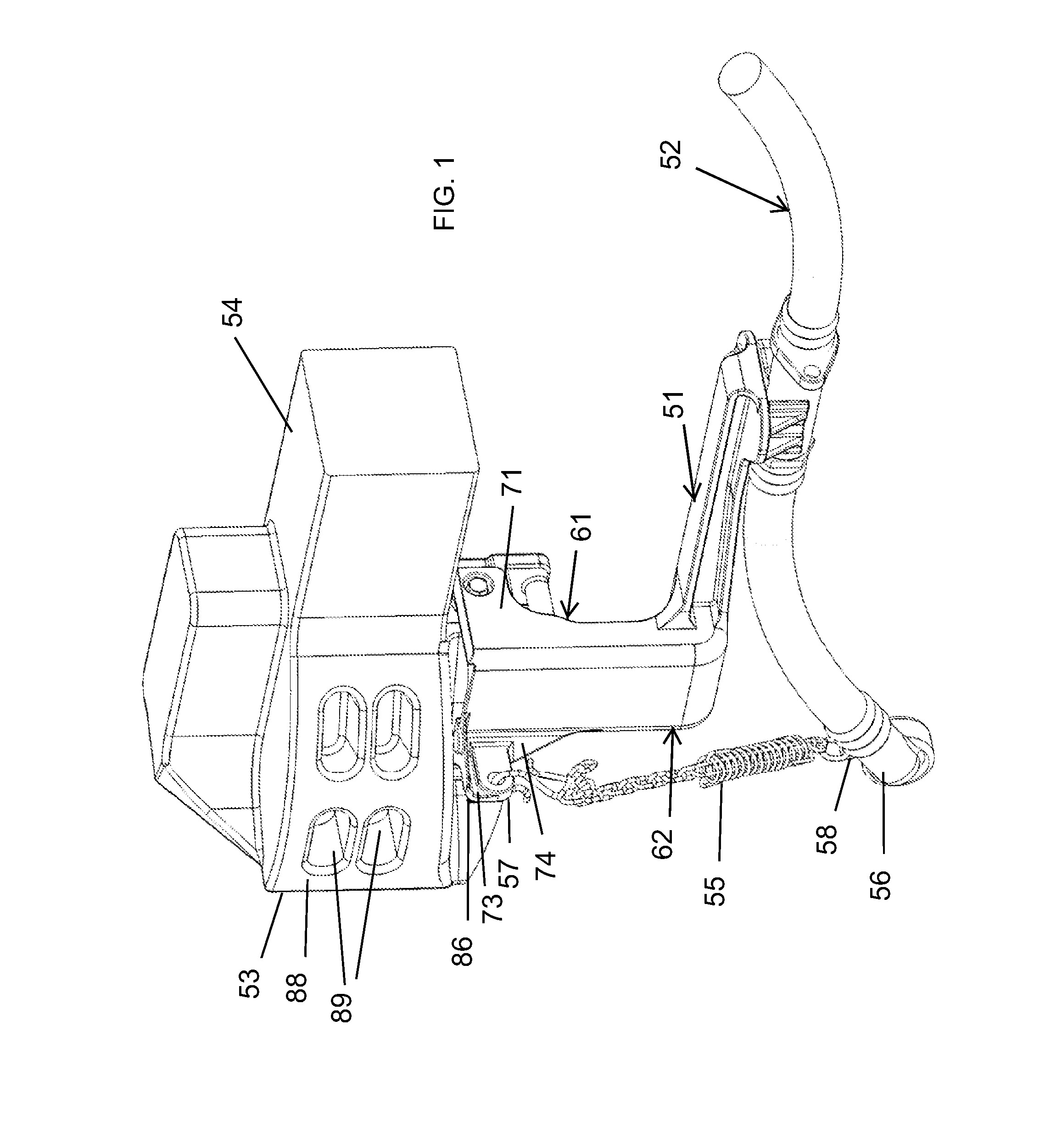
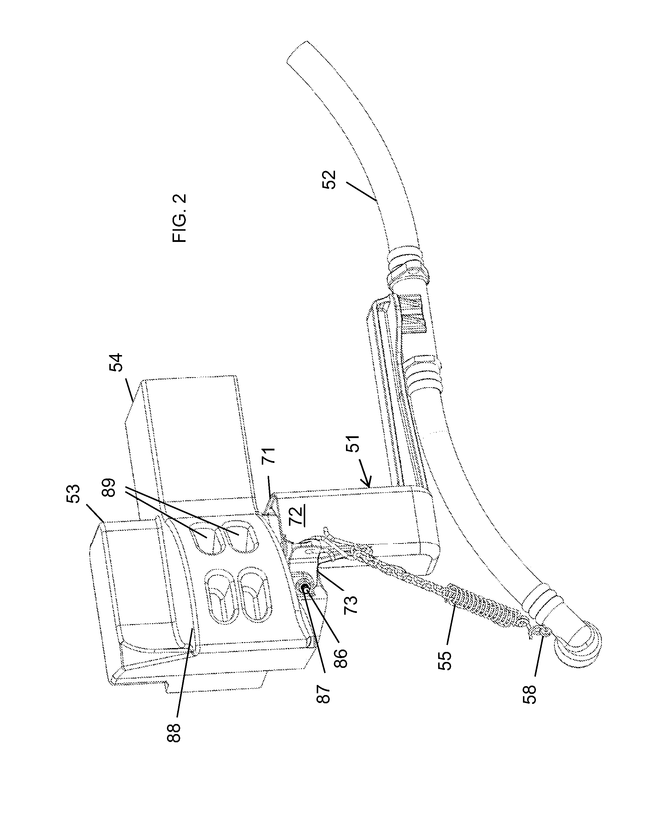
[0062]FIG. 1 and FIG. 2 illustrate an embodiment of a railway car air brake hose support bracket or bracket assembly, generally designated at 51. This support bracket 51 is illustrated in its in-use condition by which one end of the bracket 51 is attached to a railway hose assembly generally designated at 52, while its other end is attached to a railway car coupler generally designated at 53. Coupler 53 and its shank 54 are secured to the railway car (not shown), typically through a yoke (not shown...


PUM

PropertyMeasurementUnit
bevel angleaaaaaaaaaa
angleaaaaaaaaaa
movementaaaaaaaaaa

Abstract

A railway car air brake hose support bracket has an upper portion with first and second attachment members, a lower portion and an air hose connector. The first attachment member enters into and engages a portion of an accessible compartment of an uncoupling mechanism housing below the coupler head, and the second attachment member is secured to an air brake hose support lug of the railway car coupler. The air brake hose connector engages an air brake hose assembly and suspends this hose assembly from the railway coupler at a predetermined distance above the rail bed. A method of installing the hose support bracket includes positioning the first and second attachment members, securing them in place, and attaching one or more railway brake hose units to the air hose connector, either before or after this positioning and securing of the upper portion of the bracket.

Description

BACKGROUND[0001]1. Field of the Disclosure[0002]The present subject matter relates to supports for railway car air brake hoses, and particularly to railway car air brake hose support brackets that are attached to a railway car coupler and provide support for air brake hose assemblies, which brackets are especially suitable for so-called cushioned railway cars in that the hose support brackets move with the railway car coupler.[0003]2. Description of Related Art[0004]Suspension devices for railway car air brake hose assemblies are known for suspending the hose assemblies from a variety of different locations of a railway car, including frames, bodies, coupler yokes and couplers themselves. Some suspension devices are intended to allow controlled and limited vertical movement of the air brake hose assemblies that they suspend, such as those resembling flexible and / or adjustable straps. A typical function of such devices is to provide a secondary or safety support mechanism for the air...

Claims


Application Information

Patent Timeline
Patent Type & Authority Applications(United States)
IPC IPC(8): F16L3/12B61H11/06F16L3/127
CPCF16L3/1222B61H11/06F16L3/1218F16L3/127B61H13/34B60T17/046B61G5/08
Inventor MAKI, BRIAN G.
Owner IRECO INC
Why Eureka
Try Eureka