
Method and system for determining a region of interest for an imaging device based on instrument landing system

a technology of instrument landing system and imaging device, which is applied in the field of electronic landing system, can solve the problems of limited performance and limit the effect of image enhancemen

Active Publication Date: 2016-05-05
ELBIT SYST LTD
View PDF8 Cites 3 Cited by
  • Summary
  • Abstract
  • Description
  • Claims
  • Application Information

AI Technical Summary

Benefits of technology

The present invention provides a system for identifying a specific region of interest for an imaging device on an aircraft based on an instrument landing system (ILS). This system uses an ILS detector to identify the position of the aircraft, and calculates a line of sight between the aircraft and a planned touchdown point. This calculated line of sight is used to define a region of interest, which is the area that the imaging device will focus on during the touchdown process. The system applies image processing operations only to data within this region of interest, which improves image quality and reduces data processing requirements. This system is effective in ensuring accurate and efficient touchdowns.

Problems solved by technology

Currently, limiting the image enhancement is carried out by determining the planned touchdown position based on global positioning systems (GPS) and other location based orientation means.
GPS service is not always available and may sometimes lead to limited performance.

Method used


Image

  • Method and system for determining a region of interest for an imaging device based on instrument landing system
  • Method and system for determining a region of interest for an imaging device based on instrument landing system
  • Method and system for determining a region of interest for an imaging device based on instrument landing system

Examples


Embodiment Construction

[0013]With specific reference now to the drawings in detail, it is stressed that the particulars shown are for the purpose of example and solely for discussing the preferred embodiments of the present invention, and are presented in the cause of providing what is believed to be the most useful and readily understood description of the principles and conceptual aspects of the invention. In this regard, no attempt is made to show structural details of the invention in more detail than is necessary for a fundamental understanding of the invention. The description taken with the drawings makes apparent to those skilled in the art how the several forms of the invention may be embodied in practice.

[0014]Before explaining the embodiments of the invention in detail, it is to be understood that the invention is not limited in its application to the details of construction and the arrangement of the components set forth in the following descriptions or illustrated in the drawings. The inventi...


PUM


Abstract

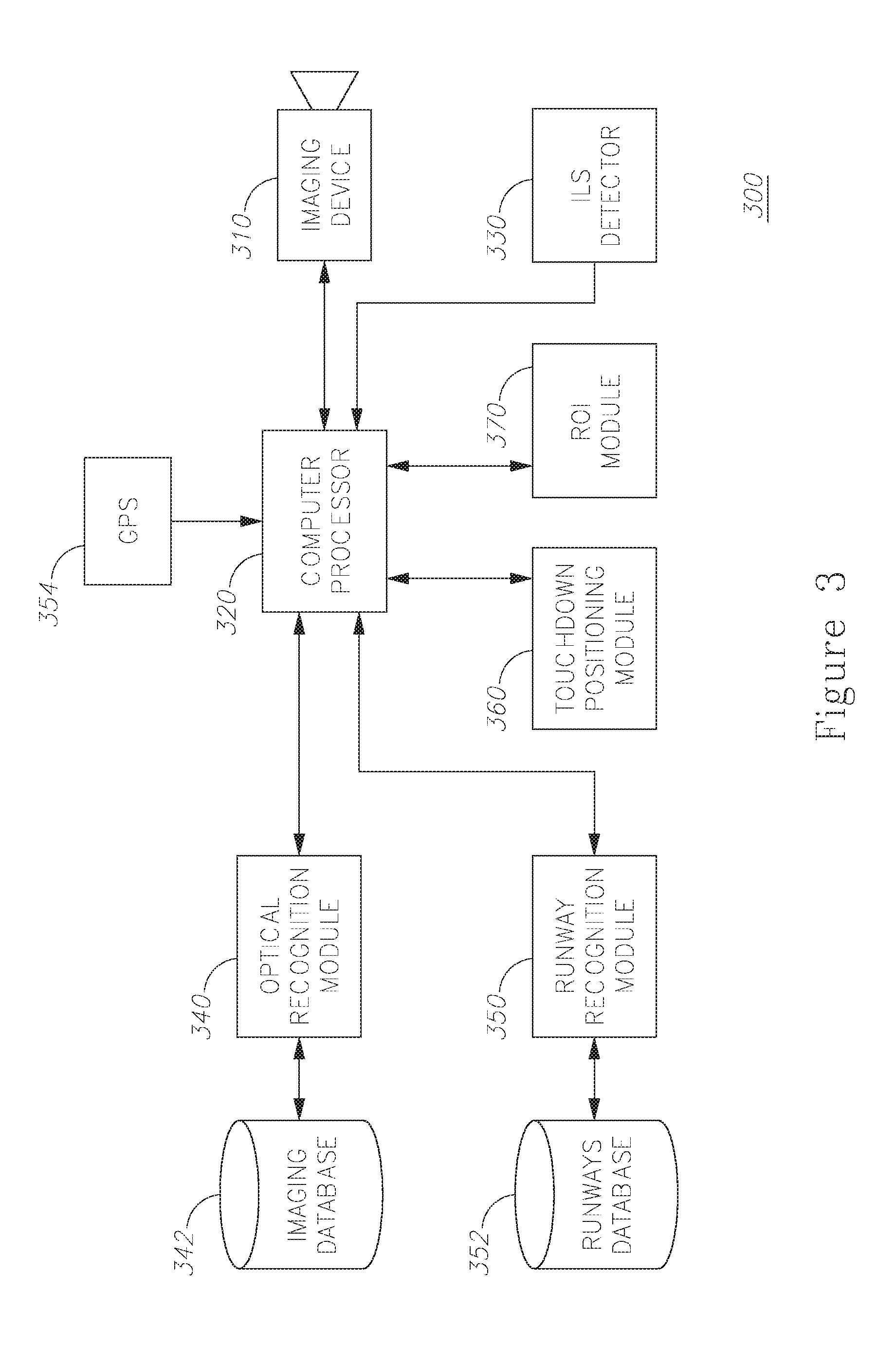
A system for determining a region of interest for an imaging device based on instrument landing system (ILS) is provided herein. The system may include an imaging device attached to an aircraft; an ILS detector; a computer processor configured in to calculate in a line of sight between said aircraft and a planned touch down point, based on the received ILS signals; a touchdown positioning module executed by the computer processor and configured to calculate a position in a field of view (FOV) of said imaging device which represents the planned touchdown point, based on said line of sight; and a region of interest (ROI) module executed by the computer processor and configured to define a region of interest (ROI) of the imaging device based on said position in said FOV, wherein said computer processor is further configured to apply an image processing operation only to data within said ROI.

Description

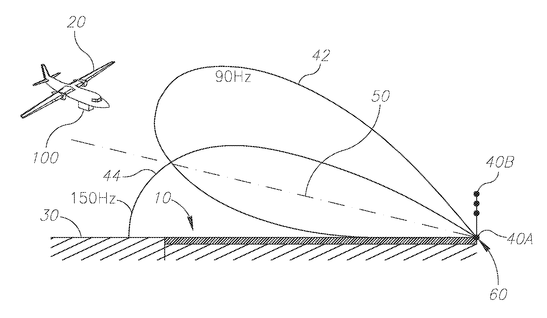
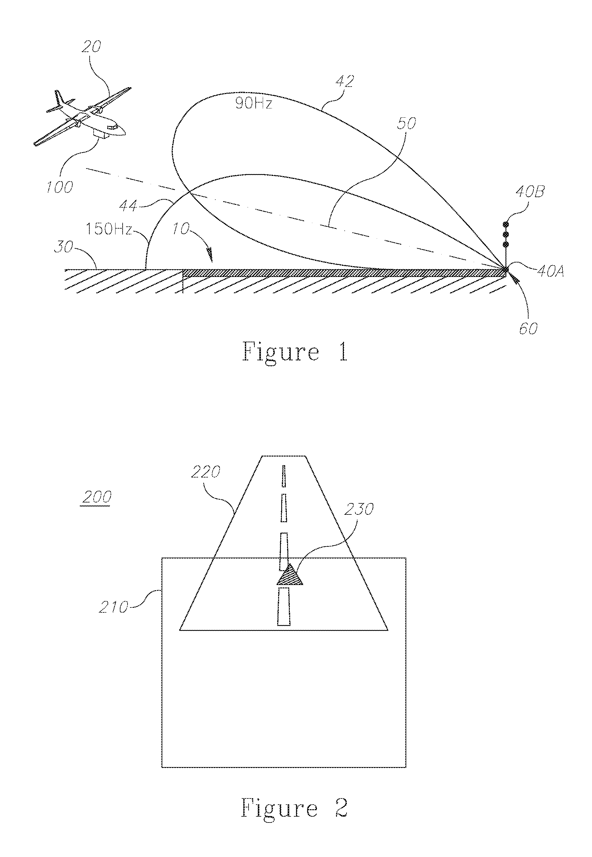
FIELD OF THE INVENTION[0001]The present invention relates generally to the field of electronic landing systems and in particular to systems and methods for improving image acquisition of an imaging device that is usable in aircraft landing.BACKGROUND OF THE INVENTION[0002]Instrument landing systems are used in many runways to facilitate the landing process by providing radio frequency (RF) beams indicating the runway location as well as preferred touchdown points along it. Aircrafts equipped with ILS facilities may easily align toward landing with the optimal landing angle at the correct time.[0003]Enhance vision systems (EVS) are used to provide the pilots with a better visual display of the landing route and specifically the runway and its immediate environment. Sometimes, augmented reality such as visual symbol indicated is presented over a portion of the image presented to the pilot. It is desirable that the portion of the image presented to the pilot would be restricted only to...

Claims


Application Information

Patent Timeline
IPC IPC(8): G08G5/02G08G5/00G01S19/15G01S5/16H04N7/18G06T7/00
CPCG08G5/025H04N7/185G06T7/0048G08G5/0021G01S19/15G01S5/16G06T7/0081G02B27/01G02B2027/014G01S1/14G05D1/0676G06T7/77G06T7/11
Inventor HASHARONI, OMER
Owner ELBIT SYST LTD
Learn More