Method for controlling operation of an HVAC system

Active Publication Date: 2016-05-12
BELIMO HOLDING AG
View PDF9 Cites 20 Cited by
  • Summary
  • Abstract
  • Description
  • Claims
  • Application Information

AI Technical Summary

Benefits of technology

[0016]In an embodiment, the flow ratio is compared in the cloud-based HVAC control center to a threshold value, the threshold value being dependent on the defined maximum pressure threshold, and the minimum damper position is calculated depending on the comparison of the flow ratio to the threshold value.
[0017]In another embodiment, calculating the minimum damper position includes calculating in the cloud-based HVAC control center a pressure ratio using the total flow in the HVAC system and calibration flow values stored in the cloud-based HVAC control center, the calibration flow values indicating the flow of air through a damper at the defined calibration pressure in the HVAC system and at the current damper position of the respective damper, and calculating the minimum damper position for the actuators by comparing in the cloud-based HVAC control center the pressure ratio to a threshold value, the threshold value being dependent on the defined maximum pressure threshold, and calculating the minimum damper position depending on the comparison of the pressure ratio to the threshold value.
[0018]In a further embodiment, demand data is transmitted from the HVAC system via the telecommunications network to the cloud-based HVAC control center. The demand data is indicative of air flow requirements of the zones of the HVAC system. Using the current damper position values from the actuators, the damper having the largest current opening is determined in the cloud-based HVAC control center. A defined maximum damper position is set in the cloud-based HVAC control center for the damper having the largest current opening. Using the demand data and the flow measurement values, an adjusted fan speed is calculated in the cloud-based HVAC control center for a fan in the HVAC system, such that a demand is met for the zone associated with the damper having the largest current opening. The adjusted fan speed is transmitted from the cloud-based HVAC control center via the telecommunications network to the fan in the HVAC system.
[0019]In an embodiment, an HVAC control report is generated in the cloud-based HVAC control center and the HVAC control report is transmitted from the cloud-based HVAC control center via the telecommunications network to a communication terminal registered in the cloud-based HVAC control center for the HVAC system. For example, the HVAC control report includes control values for the actuators as calculated by the cloud-based HVAC control center.
[0020]In additi

Problems solved by technology

In variable air volume (VAV) HVAC systems with multiple zones, the closing of all dampers leads to possible mechanical damage of the duct work and often to an inacceptable noise level.
Furthermore, if all dampers but one are closed, the regulation of the flow bec

Method used


Image

  • Method for controlling operation of an HVAC system
  • Method for controlling operation of an HVAC system
  • Method for controlling operation of an HVAC system

Examples


Embodiment Construction

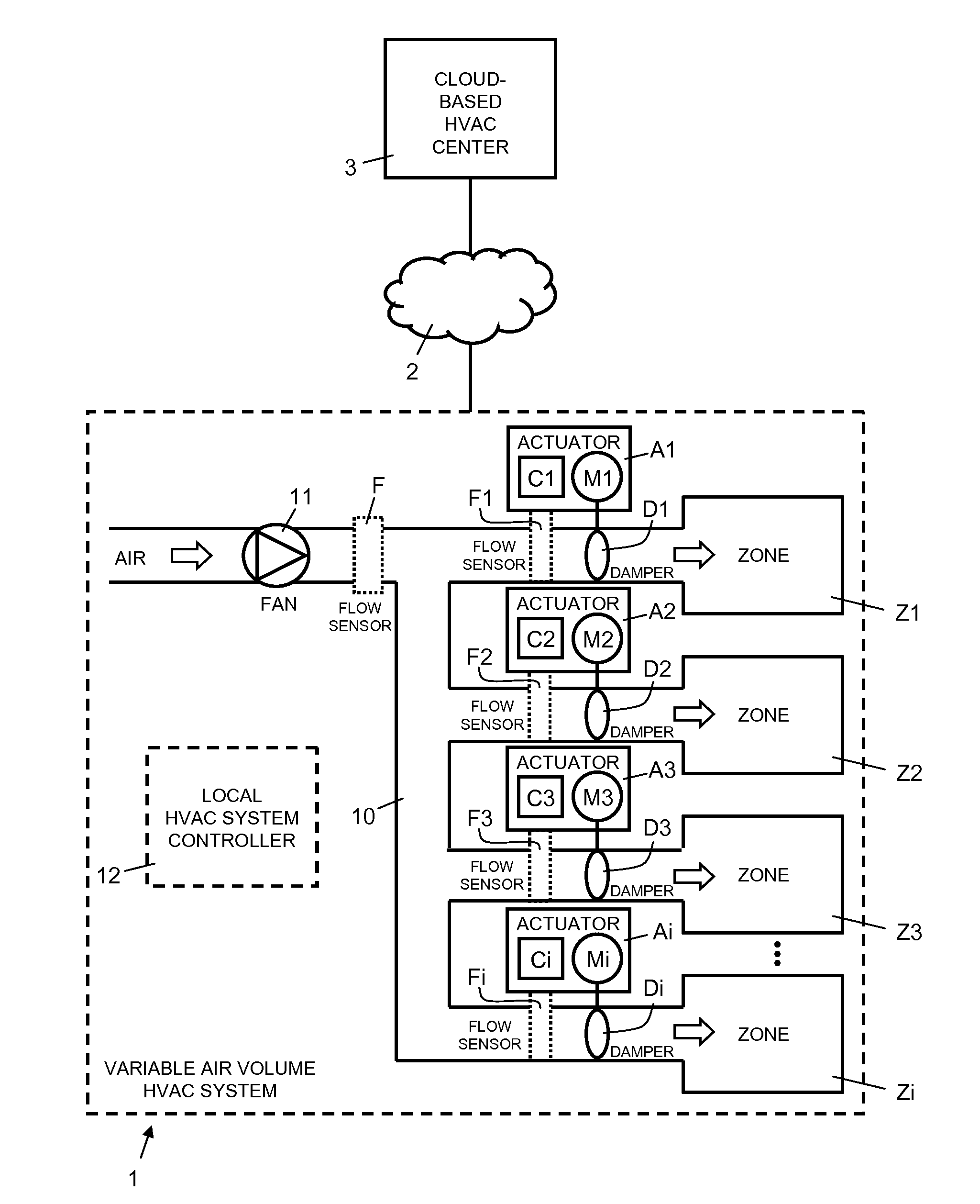
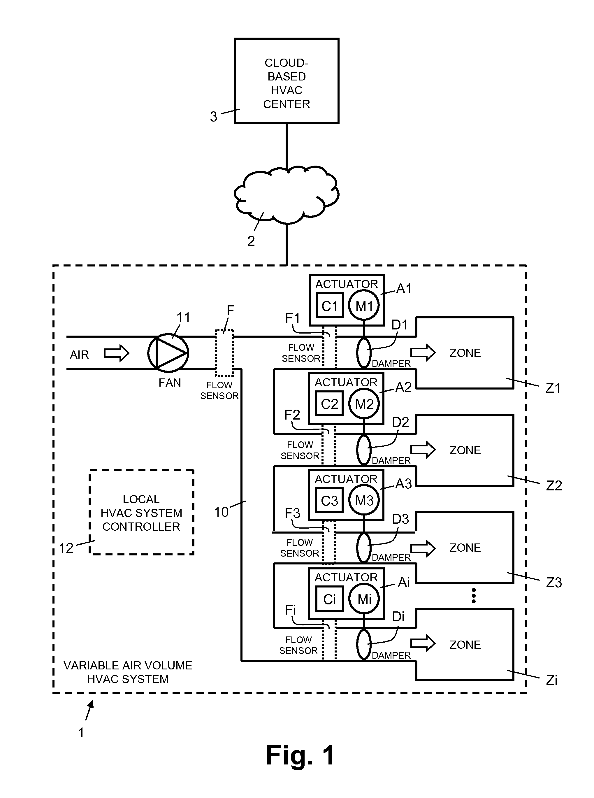
[0027]In FIG. 1, reference numeral 1 refers to an HVAC system, e.g. a variable air volume (VAV) HVAC system. The HVAC system 1 includes fluid transporting system 10, e.g. an air transporting system 10 with air ducts and pipes for delivering air to a plurality of zones Z1, Z2, Z3, Zi, e.g. enclosed spaces or rooms in a building, for the purpose of heating, ventilating, cooling, and / or air conditioning (HVAC). The air is moved by way of at least one motorized fan 11 arranged in the air transporting system 10. One skilled in the art will understand that in a liquid based HVAC system a pump is used instead of a fan. The flow of air into each of the zones Z1, Z2, Z3, Zi is adjusted and regulated by a respective damper D1, D2, D3, Di arranged in the air transporting system 10. The dampers D1, D2, D3, Di are driven by respective actuators A1, A2, A3, Ai in a range from a minimum damper position Posmin to a maximum damper position Posmax. One skilled in the art will understand that in a liq...


PUM


Abstract

For controlling the flow of air into the zones (Z1, Z2, Z3, Zi) of a variable air volume HVAC system (1) having actuator driven dampers (D1, D2, D3, Di), which operate in a range from a minimum damper position to a maximum damper position for adjusting the flow of air into a zone (Z1, Z2, Z3, Zi), flow measurement values and current damper positions are transmitted via a telecommunications network (2) to a cloud-based HVAC control center (3). Using the flow measurement values and calibration values, which indicate HVAC system parameters at a defined calibration pressure in the HVAC system (1) and at different damper positions, the cloud-based HVAC control center (3) calculates the minimum damper position for the actuators (A1, A2, A3, Ai), such that the pressure in the HVAC system (1) does not exceed a defined maximum pressure threshold, and transmits the minimum damper position to the actuators.

Description

FIELD OF THE INVENTION[0001]The present invention relates to a method and a system for controlling operation of an HVAC (Heating, Ventilation and Air Conditioning) system. Specifically, the present invention relates to a method and a system for controlling operation of an HVAC system having actuator driven valves for adjusting the flow of fluid in the HVAC system and one or more sensors for sensing operational parameters of the HVAC system.BACKGROUND OF THE INVENTION[0002]In HVAC systems, zoning is becoming increasingly popular in residential buildings as it allows a finer regulation of the temperature and flow of energy. The flow of fluid, e.g. air, i.e. its amount or volume, into a zone, e.g. an enclosed space or room in a building, is controlled by an actuated valve or damper. The position of the valve or damper is controlled depending on the measurement of the thermostat in each zone and demand, e.g. a desired temperature in the zone. The demand is set by a user or by a computer...

Claims


Application Information

Patent Timeline
IPC IPC(8): F24F11/00G05B15/02F24F3/044
CPCF24F11/0012F24F11/0076G05B15/02F24F2011/0041F24F3/0442F24F2011/0056F24F2011/0063F24F2011/0071F24F11/006F24F2011/0046F24F11/62F24F11/30F24F11/70H04L12/2818F24F2140/50F24F11/64F24F11/58F24F2110/40F24F2140/40F24F11/63F24F11/38F24F11/80F24F11/77F24F11/74H04L67/12H04L67/10H04L67/101F24F2110/10Y02B30/70
Inventor SCHMIDLIN, PETER
Owner BELIMO HOLDING AG
Why Eureka
Try Eureka