
Directional climate control system with infrared targeting

a climate control system and infrared technology, applied in the direction of lighting and heating equipment, instruments, transportation and packaging, etc., can solve the problems of increased blower fan noise, complex thermodynamic environment in the interior of the vehicle, and inability to optimize the best control of the hvac system

Active Publication Date: 2016-03-24
FORD GLOBAL TECH LLC
View PDF22 Cites 26 Cited by
  • Summary
  • Abstract
  • Description
  • Claims
  • Application Information

AI Technical Summary

Benefits of technology

The invention uses thermographic imaging to detect occupants' skin surfaces and targets them with a treated air stream using electronically-controlled vents. The air stream can be directed based on detected seat occupancy, and thermographic images can be taken to update the air stream direction and flow rate under changing conditions. The invention allows for precise targeting of occupants with air, resulting in more efficient heating and cooling of the passenger compartment.

Problems solved by technology

The vehicle occupants, however, may not understand how to best control the HVAC system to optimize efficiency.
This also results in greater blower fan noise than is really necessary to achieve the desired thermal comfort.
However, the thermodynamic environment in a vehicle interior is complex, as are the relationships between various HVAC control settings and the resulting effect on skin temperature of different occupants.
Therefore, previous systems have been relatively complex and not cost effective.
However, no known system has provided sufficient accuracy or performance to truly optimize directional adjustment of treated air over a sufficiently wide range of thermal conditions.

Method used


Image

  • Directional climate control system with infrared targeting
  • Directional climate control system with infrared targeting
  • Directional climate control system with infrared targeting

Examples


Embodiment Construction

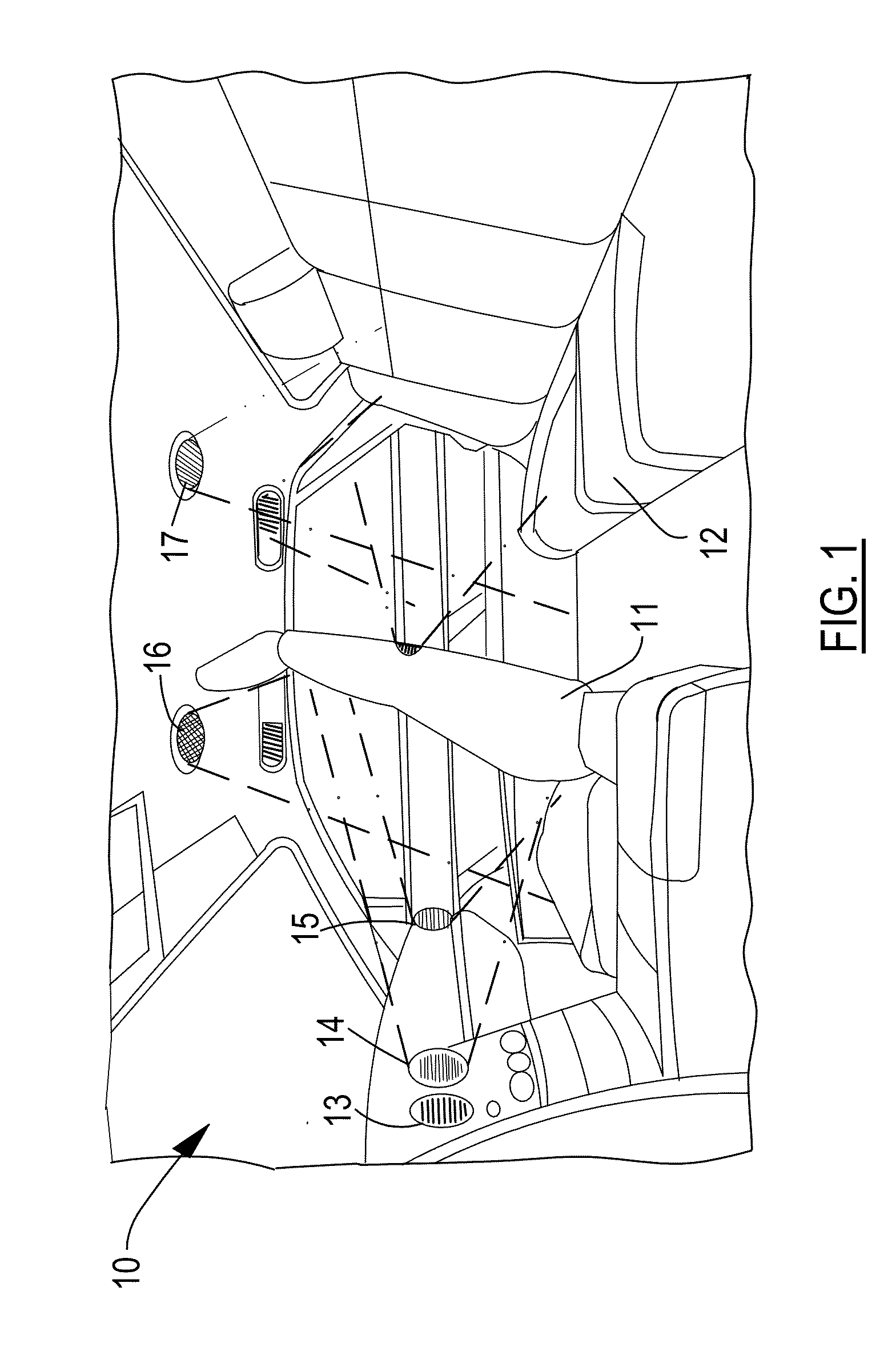
[0022]FIG. 1 shows a passenger compartment 10 of an automotive vehicle with various seating locations such as a front seat 11 and rear seats 12. A vehicle HVAC system includes a plurality of air outlets or vents 13-17 for directing respective streams of treated air into passenger compartment 10. One or more of vents 13-17 has a steerable outlet so that the direction and / or focus (i.e., spread) are automatically adjustable by the HVAC system.

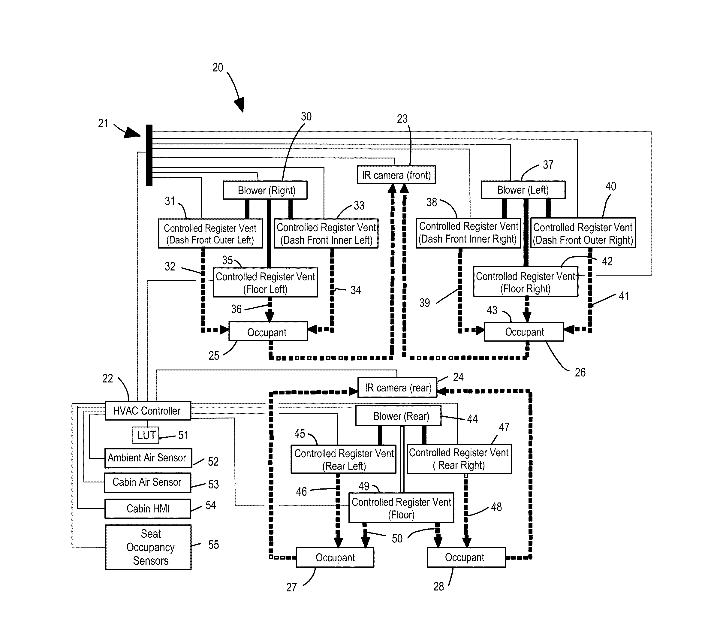
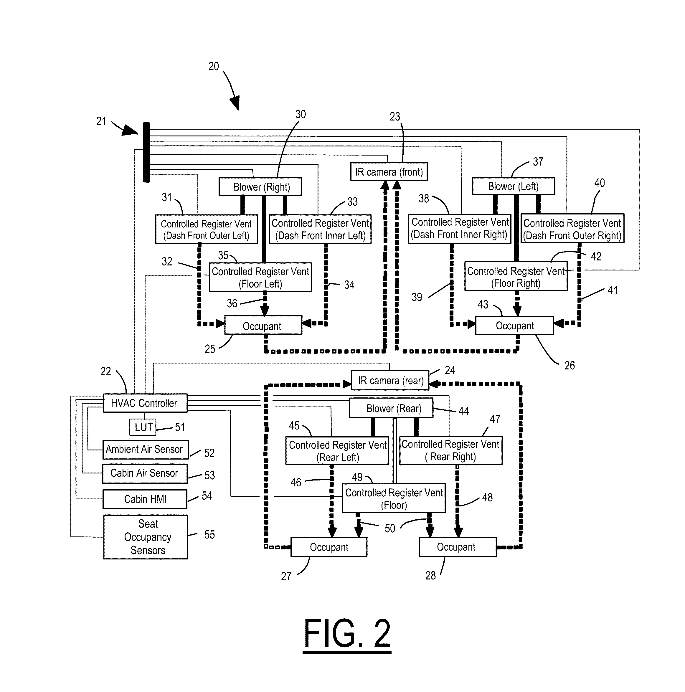
[0023]FIG. 2 shows an HVAC system 20 with various components interconnected by an electrical system 21 preferably including an electrical wiring harness and a multiplex communication system as commonly used in the industry. An HVAC control circuit 22 may preferably be comprised of a typical electronic module including customized circuits and / or one or more programmable microcontrollers with appropriate software and / or firmware as commonly deployed in automotive vehicles.

[0024]A thermographic imager, preferably taking the form of an infrared camer...


PUM


Abstract

A heating, ventilating, and air conditioning (HVAC) system has a steerable outlet for directing a stream of treated air into a passenger compartment of a vehicle. A thermographic imager is configured to capture thermographic images covering a fixed region within the passenger compartment in which an occupant is potentially located. The HVAC control circuit is configured to a) compress a thermographic image to a temperature map representing pixels of the thermographic image falling within a predetermined temperature range corresponding to the occupant, b) filter the temperature map according to a sliding window to coalesce continuous regions of pixels on average falling within the predetermined temperature range, c) quantify an area for each continuous region, d) locate a centroid of a continuous region having a largest area, and e) aim the steerable outlet toward the centroid.

Description

CROSS REFERENCE TO RELATED APPLICATIONS[0001]Not Applicable.STATEMENT REGARDING FEDERALLY SPONSORED RESEARCH[0002]Not Applicable.BACKGROUND OF THE INVENTION[0003]The present invention relates in general to automotive HVAC systems, and, more specifically, to automatic adjustment of steerable air outlets to direct treated air to optimize passenger comfort and reduce energy usage.[0004]Heating, ventilating, and air conditioning (HVAC) systems control the climate in transportation vehicles such as automobiles in order to maintain thermal comfort of the vehicle occupants. Typically, a blower passes air through heat exchangers and delivers conditioned air to various points within the passenger cabin. Warm air may be provided by a heater core obtaining heat from coolant flowing in a combustion engine, for example. Cool air may be obtained using a compressor mechanically-driven by the engine. Electrified vehicles such as hybrid electric vehicles (HEVs) and battery electric vehicles (BEVs) m...

Claims


Application Information

Patent Timeline
IPC IPC(8): B60H1/00G06V10/00
CPCB60H1/00871B60H1/00742B60H1/00G06F18/00B60H1/00028B60H1/00821F28F27/02
Inventor PERKINS, WILLIAM, PAUL
Owner FORD GLOBAL TECH LLC
Learn More