Sliding window assembly

a technology for sliding glass panes and assemblies, which is applied in the direction of door/window fittings, building components, constructions, etc., can solve the problems that no prior art arrangement has the ability to move the sliding glass pane in the closed position, and achieve the effect of facilitating facilitating the compound movement of the glass pan

Inactive Publication Date: 2006-02-16
HI-LEX CORPORATION
View PDF12 Cites 69 Cited by
  • Summary
  • Abstract
  • Description
  • Claims
  • Application Information

AI Technical Summary

Benefits of technology

[0007] According to a further feature of the invention, the guide structure includes a fixed guide structure; a moveable guide structure slidably mounted in the fixed guide structure; at least one guide pin secured to the pane; a compound slot receiving the pin; and a drive mechanism interconnecting the glass pane and the moveable guide structure and operative with the pin positioned in a first portion of the compound slot to move the glass pane along the fixed guide structure in a longitudinal direction generally parallel to the plane of the pane and operative with the pin positioned in a second portion of the compound slot to move the glass pane laterally relative to the plane of the pane. This specific guide structure facilitates the compound movement of the glass pane to its flush position.
[0008] According to a further feature of the invention, the first portion of the compound slot comprises an elongated primary portion generally parallel to the plane of the glass pane and the second portion of the compound slot comprises an end portion extending at an angle to the primary portion. This specific slot configuration further facilitates the compound movement of the glass pane.

Problems solved by technology

However, none of the prior art arrangements have had the ability to move the sliding glass pane in its closed position to a position wherein the face of the sliding glass pane is flush with the face of the fixed glass panes.

Method used


Image

  • Sliding window assembly
  • Sliding window assembly
  • Sliding window assembly

Examples


Embodiment Construction

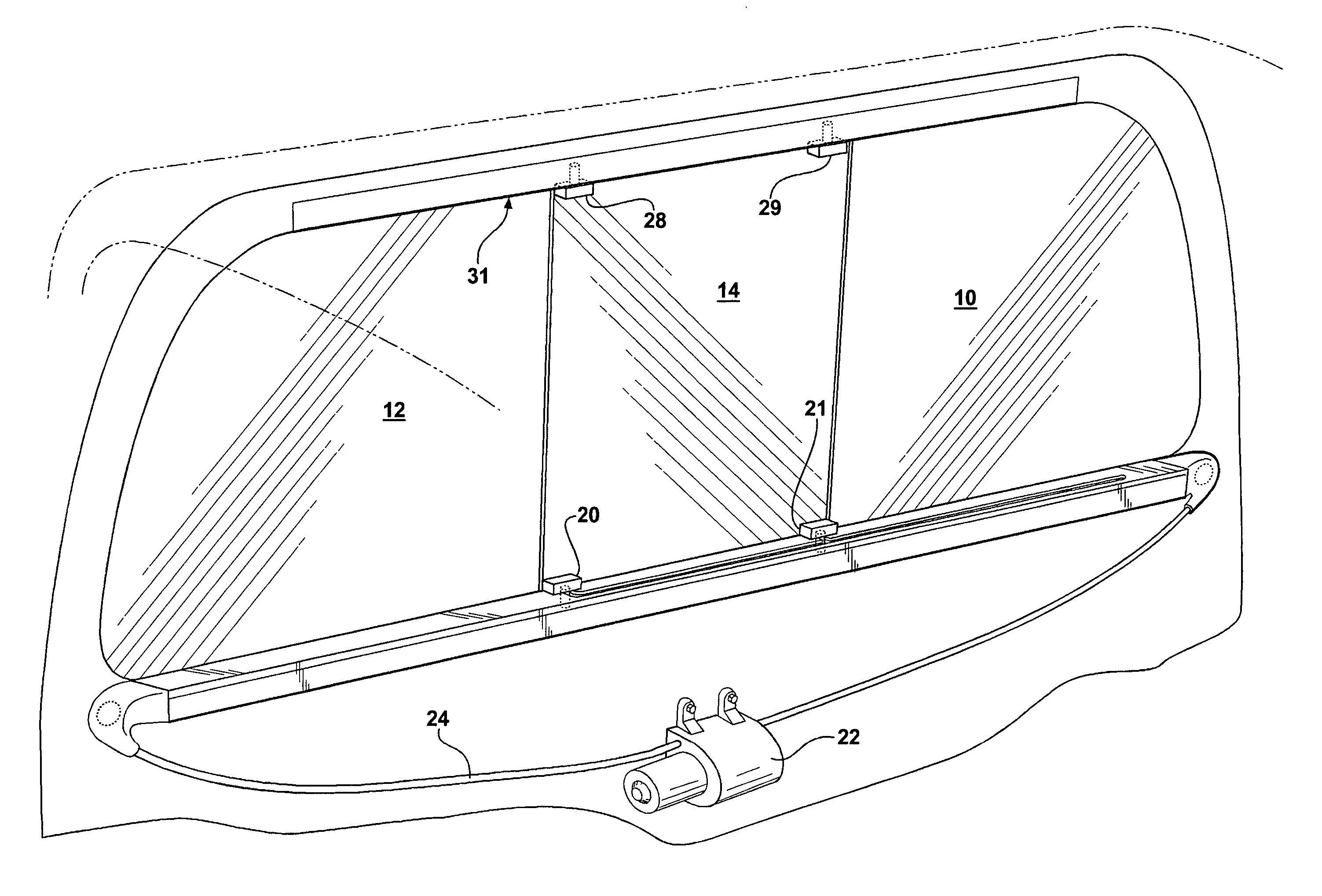
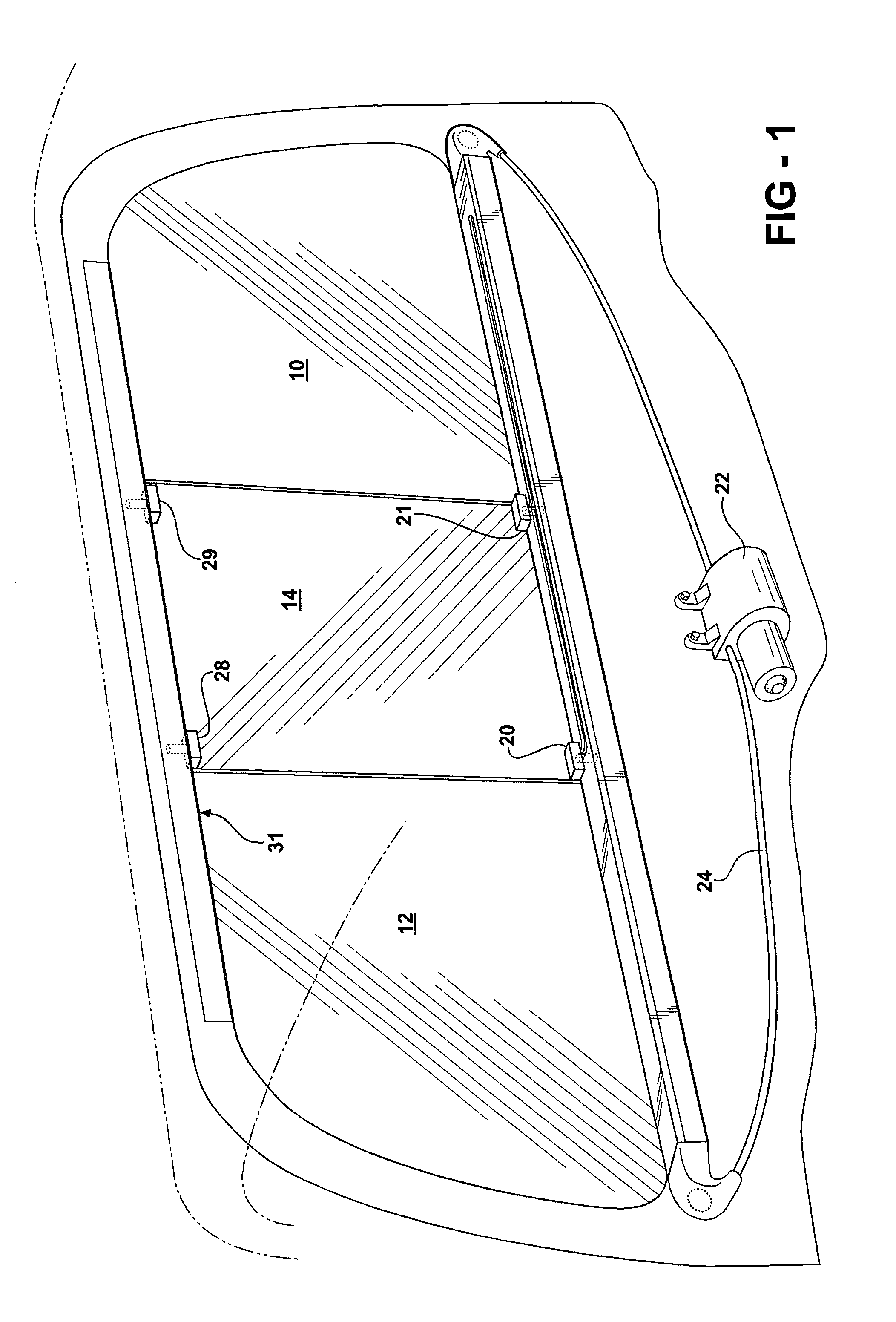
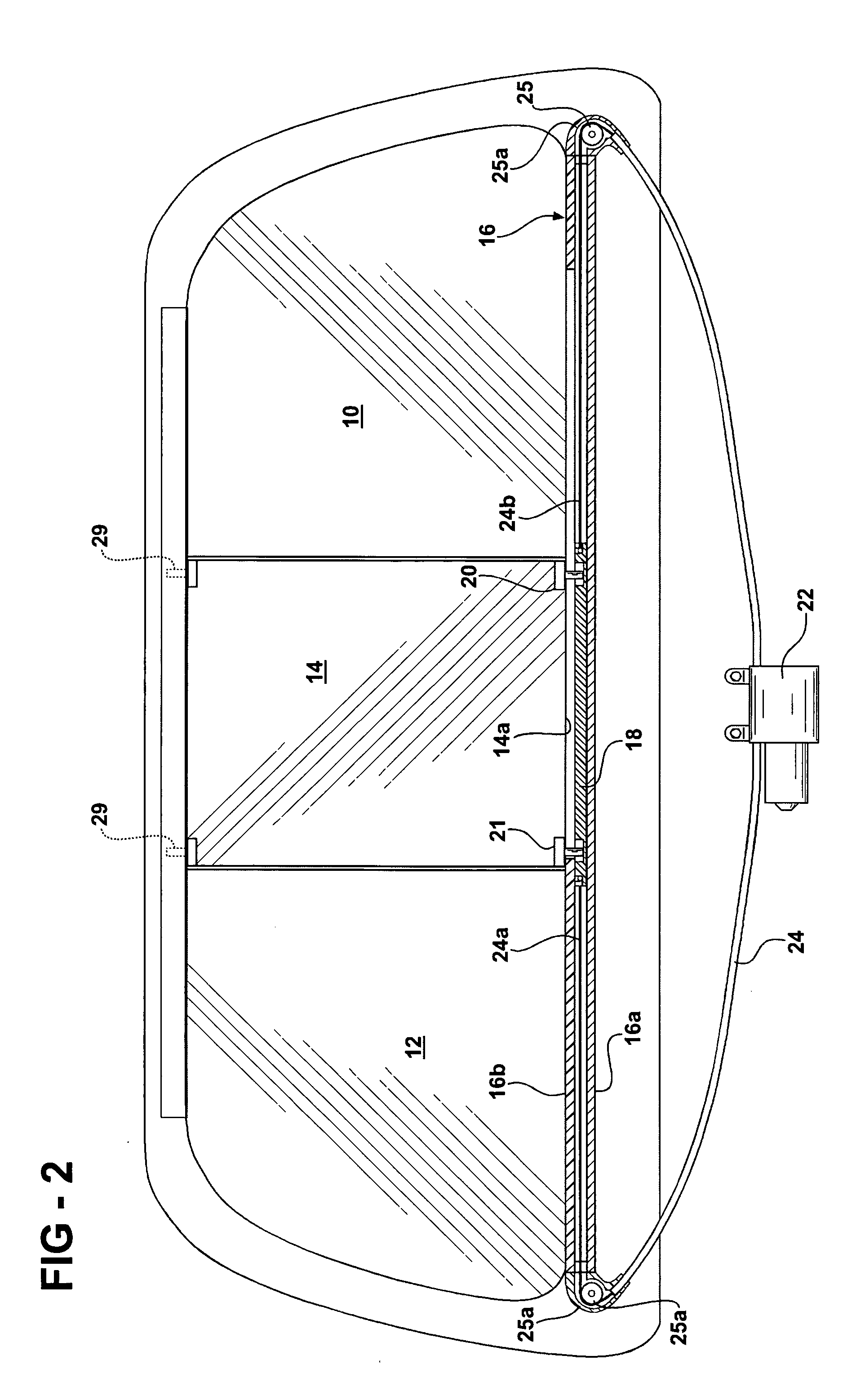
[0027] The embodiments of the invention illustrated in FIGS. 1-18 relate to the application of the invention to a sliding window assembly constituting the rear window in the cab of a pickup type motor vehicle.

[0028] With reference to FIGS. 1-8, the sliding window assembly of the invention is seen embodied as the rear window of the cab of a pickup type motor vehicle with FIGS. 1 and 2 being taken from inside the cab looking rearwardly.

[0029] The rear window assembly seen in FIGS. 1 and 2 comprises, broadly considered, a left fixed window pane 10, a right fixed window pane 12, and a moveable or sliding window pane 14 adapted to be moved between the closed position seen in FIGS. 1 and 2, in which it is positioned between fixed panes 10 and 12 to close the rear window assembly, and an open position in which it is positioned behind the fixed pane 10.

[0030] The movement of the sliding pane 14 between its open and closed position is accomplished utilizing a mechanism comprising a fixed ...


PUM


Abstract

A sliding window assembly for use with a motor vehicle such for example as the rear window of the cab of a pickup type truck. A guide structure mounts a sliding pane for longitudinal sliding movement generally parallel to the plane of the pane between an open position and a closed position, and a lateral thrust mechanism is provided which is operative in response to arrival of the pane in its closed position to thereafter move the pane laterally relative to the plane of the pane into a position wherein the exposed face of the pane is flush with a surrounding vehicle surface such for example as the surface defined by fixed panes in the rear window of a pickup truck. The lateral movement of the pane is accomplished by a guide pin on the glass received in a compound guide slot defined by a fixed guide structure, a slider slidably mounted in a fixed guide structure for movement parallel to the plane of the pane, and a drive mechanism interconnecting the pane and the slider and operative with the pin positioned in a first portion of the compound slot to move the glass along the fixed guide structure in a direction generally parallel to the plane of a pane and operative with the pin positioned in a second angled portion of the compound slot to move the glass pane laterally relative to the plane of the pane.

Description

BACKGROUND OF THE INVENTION [0001] This invention relates to motor vehicle window assemblies and more particularly to a motor vehicle window assembly including a sliding glass pane moveable between open and closed positions. [0002] There are many motor vehicle applications wherein it is desirable to move a glass pane in a sliding fashion between an open and a closed position. For example, the rear window in a pickup type truck may comprise fixed left and right glass panels and a sliding panel adapted to move between an open position behind one of the fixed glass panels and a closed position in which it is positioned between the fixed panels to seal the window opening. [0003] Many arrangements have been proposed to facilitate the sliding movement of the sliding glass pane between its open and closed positions. However, none of the prior art arrangements have had the ability to move the sliding glass pane in its closed position to a position wherein the face of the sliding glass pane ...

Claims


Application Information

Patent Timeline
Patent Type & Authority Applications(United States)
IPC IPC(8): E05D15/10
CPCE05F15/646E05Y2900/516
Inventor ARIMOTO, SHIGEKIBERKLICH, LOUIS WILLIAM JR.COOK, BEAU JAMES JR.
Owner HI-LEX CORPORATION
Why Eureka
Try Eureka