
Connector

a technology of connecting rods and connectors, applied in the direction of coupling devices, two-part coupling devices, electric discharge tubes, etc., can solve problems such as difficult operation, and achieve the effects of preventing the housing from falling, easy unfastening, and easy unfastening of the lock lever

Active Publication Date: 2016-05-12
IRISO ELECTRONICS CO LTD
View PDF6 Cites 1 Cited by
  • Summary
  • Abstract
  • Description
  • Claims
  • Application Information

AI Technical Summary

Benefits of technology

The invention aims to provide a connector that allows for easy unfastening of a lock lever from a flat conductor even if there is no space near the connector. This simplifies the unallin process and improves efficiency.

Problems solved by technology

However, when other mounted components are closely disposed in the vicinity of the connector that is mounted on the substrate, such operations are difficult to perform.

Method used


Image

  • Connector
  • Connector
  • Connector

Examples


embodiment (figs.1 to 12)

Embodiment (FIGS. 1 to 12)

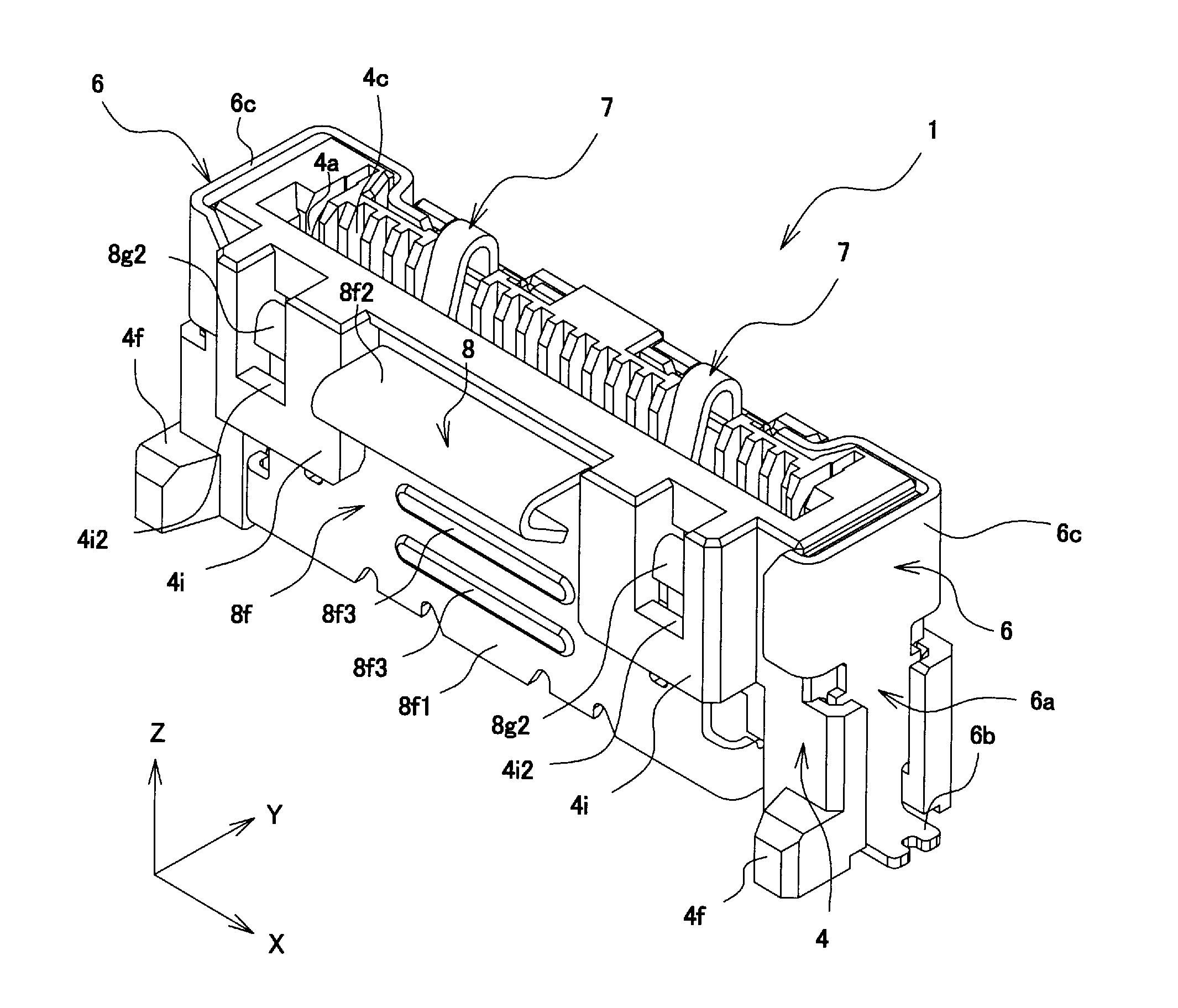
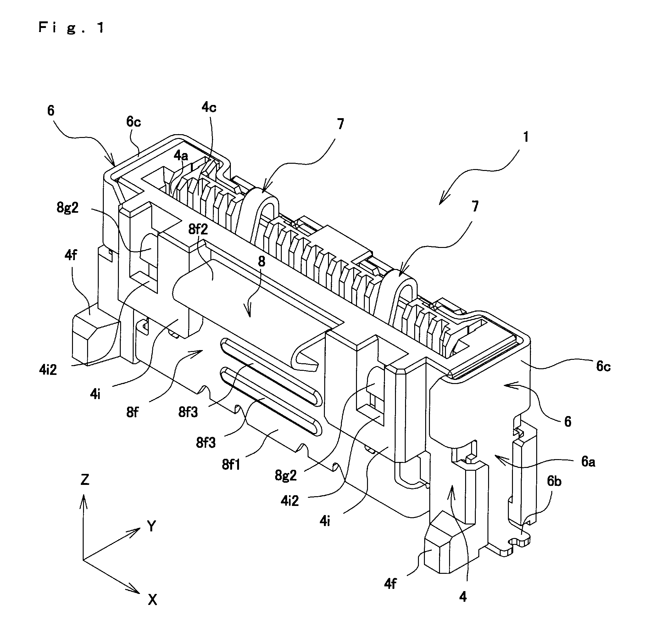
[0048]The connector 1 according to the embodiment is a connector in which, with the connector 1 being vertically placed on and secured to the substrate 2, the flat conductor 3 is inserted to electrically connect the substrate 2 and the flat conductor 3 to each other. The length of the connector 1 in the front-back direction is less than the length of the connector 1 in the height direction Z. The flat conductor 3 is inserted into a fitting chamber 4b along the height direction Z from an insertion opening 4a that is provided in the upper side of the connector 1.

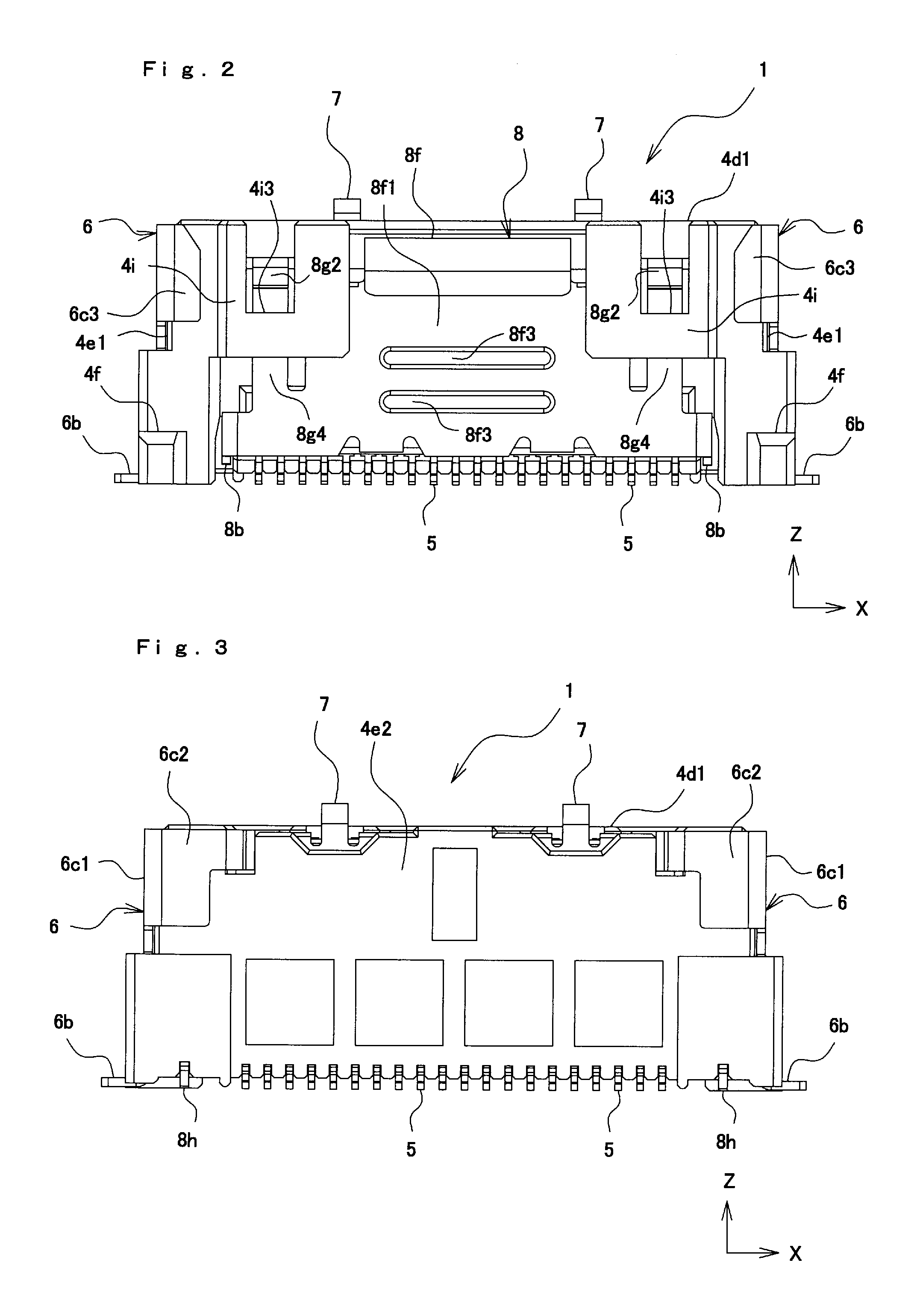
[0049]The connector 1 is mounted on the substrate 2, and electrically connects the flat conductor 3 and the substrate 2 to each other. As shown in FIGS. 1 to 6, the connector 1 includes a housing 4, terminals 5, the reinforcing members 6, ground terminals 7, and a lock lever 8.

[0050]First, a structure of the flat conductor 3, which is an object to be connected to the connector 1, according to the embo...


PUM


Abstract

A connector includes a lock lever that is fastened to a flat conductor and that maintains electrical connection between a terminal and the flat conductor. The lock lever includes a fastening portion that, in an interior of a fitting chamber, is fastened to the flat conductor that electrically contacts the terminal, and prevents removal of the flat conductor; an elastic portion that displaces the fastening portion in directions towards and away from the flat conductor; and an operation portion that includes a flat plate portion and a connecting portion, the flat plate portion extending along a front wall, the connecting portion extending from the flat plate portion in the direction away from the flat conductor and connected to the elastic portion. The flat plate portion is pushed along an insertion direction of the flat conductor, so that the connecting portion pushes the elastic portion in the direction away from the flat conductor and the fastening portion is displaced in the direction away from the flat conductor to unfasten the lock lever from the flat conductor.

Description

BACKGROUND OF THE INVENTION[0001]1. Field of the Invention[0002]The present invention relates to a connector that electrically connects a flat conductor and a substrate to each other.[0003]2. Description of the Related Art[0004]Hitherto, as a connector that is used in an electronic device, a connector that is mounted on a substrate and that electrically connects, for example, a flexible printed circuit (FPC) or a flexible flat cable (FFC) (such circuits are referred to as “flat conductor” in the specification and claims) and the substrate to each other is used. Since such a connector is capable of connecting the substrate and a unit in a device, such as a computer or a liquid crystal display, in various forms, such a connector is installed in many electronic devices.[0005]As such a connector, a connector including a lock lever that includes a fastening portion that is fastened to a recessed portion of a side edge of a flat conductor is available. In a state in which the flat conduct...

Claims


Application Information

Patent Timeline
Patent Type & Authority Applications(United States)
IPC IPC(8): H01R12/77
CPCH01R12/771H01R12/774H01R12/79
Inventor TAKANE, TORU
Owner IRISO ELECTRONICS CO LTD
Learn More