Printing cylinder assembly for a printing machine

a printing machine and cylinder technology, applied in printing presses, printing presses, rotary intaglio printing presses, etc., can solve the problems of backlash and axial deflection achieve the effect of keeping the rotational balance of the sleeve cylinder, increasing the rotation rate, and printing at a higher speed

Inactive Publication Date: 2017-04-25
MIYAKOSHI PRINTING MACHINERY
View PDF16 Cites 0 Cited by
  • Summary
  • Abstract
  • Description
  • Claims
  • Application Information

AI Technical Summary

Benefits of technology

[0011]According to the printing cylinder assembly of the invention constructed as mentioned above, by means of the shaft fastening mechanism by which the shaft mounting bore formed at the other axial end side of the sleeve cylinder can be frictionally fastened to the sleeve cylinder supporting outer peripheral surface at the other axial end side of the rotating shaft, in conjunction with the tapered surface formed on the one axial end side of the sleeve cylinder that can be coupled in close contact with the tapered surface formed on one axial end side of the rotating shaft, it should be noted that advantages are achieved of the capability of holding the sleeve cylinder on the rotating shaft coaxially with precision, increasing the reproducibility of the state that such precise holding is held for another sleeve cylinder exchanged and enhancing the accuracy of its holding.
[0029]According to the present invention, it should be noted that constituting a printing cylinder by a sleeve cylinder being able to be fitted on and extracted from a rotating shaft allows the sleeve cylinder advantageously to be coupled and fastened to the rotating shaft, without causing a backlash and axial deflection of the sleeve cylinder mounted and yet permitting it to be readily decoupled and unfastened.

Problems solved by technology

However, making the assembly capable of fitting a sleeve cylinder on, and extracting it from, a rotating shaft in a conventional manner, tends to cause a backlash and axial deflection of the sleeve cylinder.

Method used


Image

  • Printing cylinder assembly for a printing machine
  • Printing cylinder assembly for a printing machine
  • Printing cylinder assembly for a printing machine

Examples


Embodiment Construction

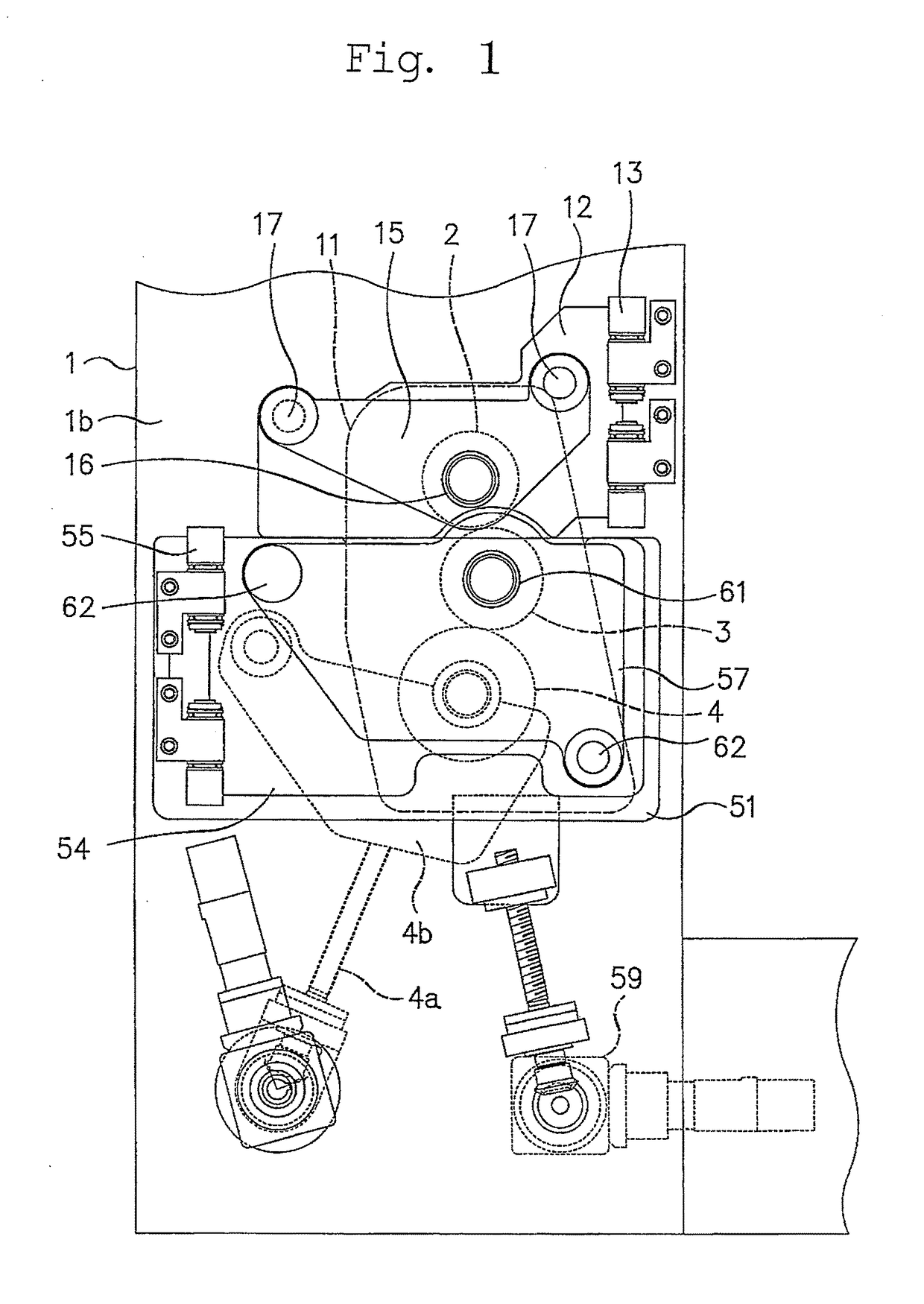
[0041]The printing machine as shown in FIG. 1 includes a main frame 1 having a plate cylinder 2, a blanket cylinder 3 and an impression cylinder 4 which are rotatably mounted on the main frame 1. The plate cylinder 2 and the blanket cylinder 3 each constitutes a printing cylinder in a printing cylinder assembly of the invention.

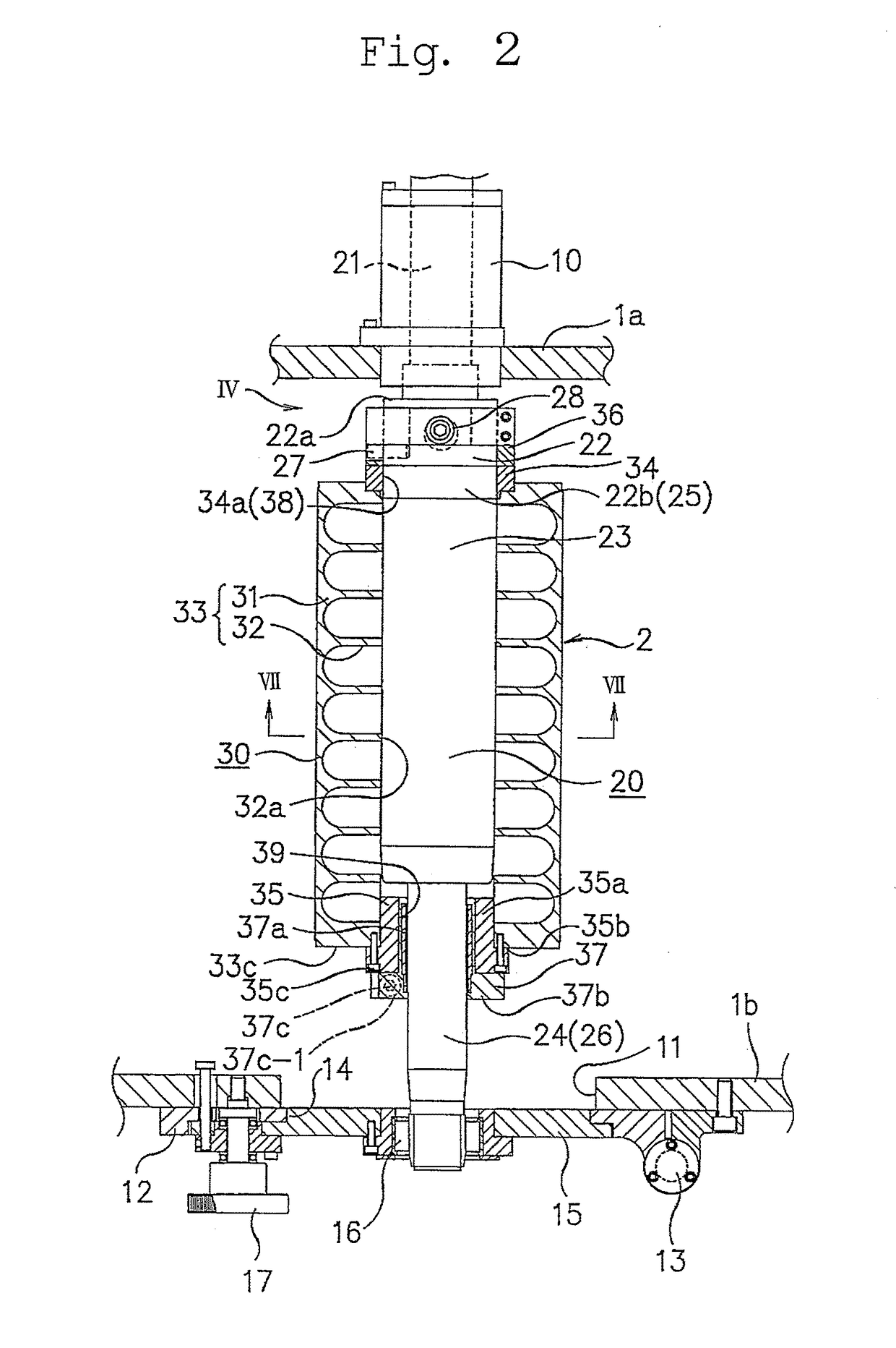
[0042]As shown in FIGS. 1, 2 and 3, the main frame 1 has one side main frame member 1a and the other side frame member 1b at one and the other sides in the axial direction of the cylinders.

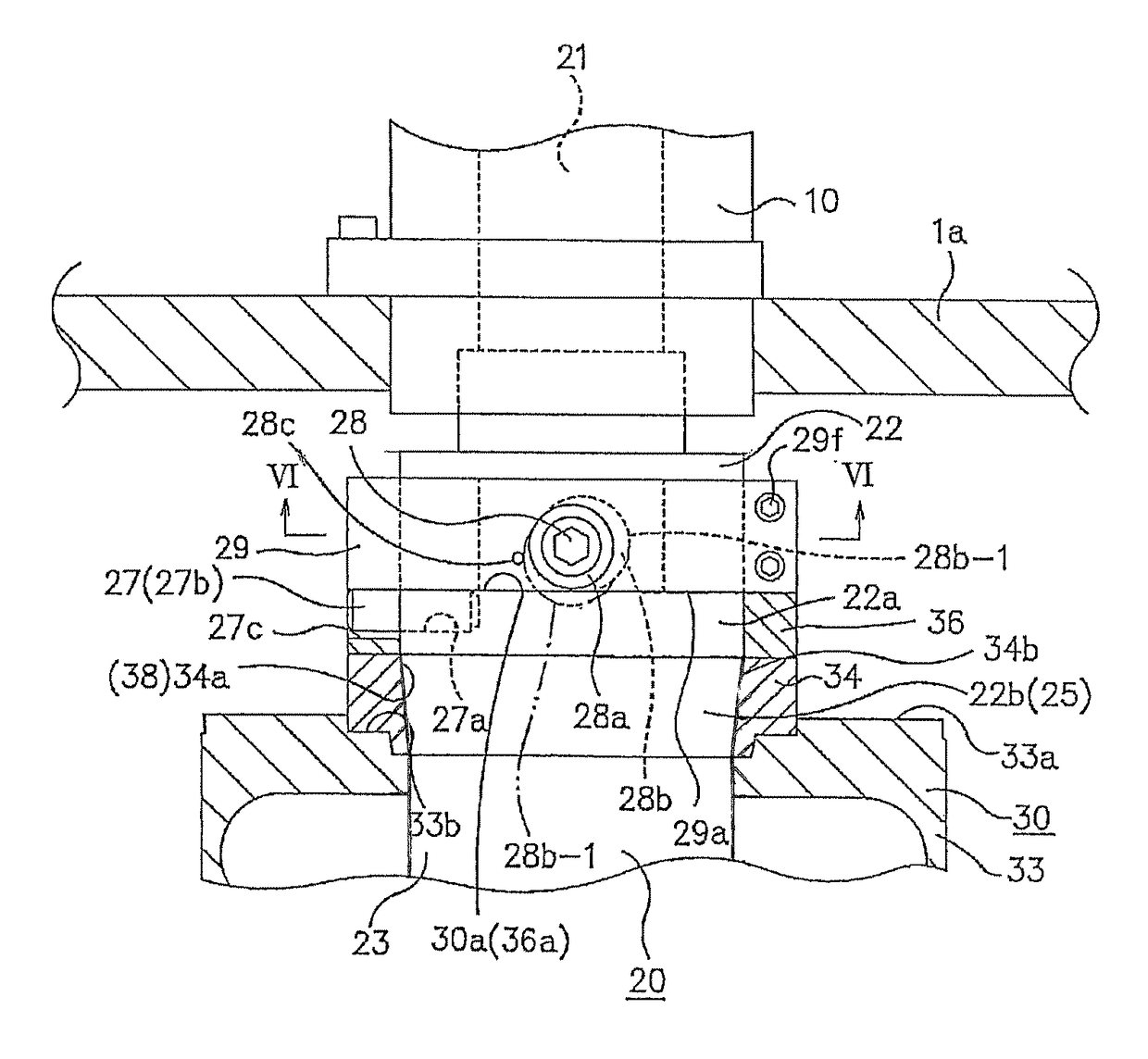
[0043]As shown in FIG. 2, in the printing cylinder assembly the plate cylinder 2 is constituted by a rotating shaft 20 and a sleeve cylinder 30 removably mounted on the rotating shaft 20 so that the sleeve cylinder 30 can be fitted on and extracted from the rotating shaft 20.

[0044]As shown in FIG. 3, the blanket cylinder 3 as with the plate cylinder 2 is constituted by a rotating shaft 20 and a sleeve cylinder 30 removably mounted on the rotating shaft 20 so that the sleeve...


PUM


Abstract

A printing cylinder assembly for a printing machine includes a rotating shaft pivotally supported at one axial end shaft section thereof in a cantilever structure, and a sleeve cylinder removably mounted on the rotating shaft so that the cylinder can be fitted on and extracted from the rotating shaft from the other axial end side of the rotating shaft. The rotating shaft is formed at one axial end side thereof with a sleeve cylinder supporting tapered surface, and the sleeve cylinder is formed at one axial end side of an inner diameter portion thereof with a tapered surface, whereby the tapered surface of the sleeve cylinder can be fitted on and in close contact with the sleeve cylinder supporting tapered surface of the rotating shaft and thereby detachably coupling one axial end portion of the sleeve cylinder with one axial end portion of the rotating shaft.

Description

BACKGROUND OF THE INVENTION[0001]Technical Field[0002]The present invention relates to a printing cylinder assembly for a printing machine in which a printing cylinder whose diameter is variable is used to produce printed images that are different in their vertical length.[0003]Background Art[0004]A printing machine designed to print on a continuous sheet or web of paper, printed images which are different in vertical length has been disclosed in JP 2004-74526 A.[0005]Such printing machines are known as a sleeve cylinder exchangeable variable printer, in which a printing cylinder comprises a sleeve cylinder removably mounted on the rotating shaft so that it can be fitted on, and be extracted from, the rotating shaft. A plurality of sleeve cylinders of different diameters are prepared for printing images of different vertical lengths and a sleeve cylinder is selected which is of a particular diameter that meets with a particular vertical size of an image to be printed. Each of such s...

Claims


Application Information

Patent Timeline
Patent Type & Authority Patents(United States)
IPC IPC(8): B41F27/10B41F27/14B41F13/10B41F13/193B41F30/04B41F3/54B41F9/18B41F3/20B41F13/20B41F13/21B41F13/44B41F27/12
CPCB41F3/54B41F13/10B41F13/193B41F13/20B41F27/1206B41F27/14B41F30/04B41P2227/21B41F3/20B41F9/18B41F13/21B41F13/44B41F27/105B41F27/1231B41P2213/802B41P2217/15
Inventor FUJIWARA, REISHITOMAKI, HITOSHIODASHIMA, KAZUMI
Owner MIYAKOSHI PRINTING MACHINERY
Why Eureka
Try Eureka