Light curtain component

Active Publication Date: 2016-05-19
PILZ AUSLANDSBETEILIGUNGEN
View PDF1 Cites 3 Cited by
  • Summary
  • Abstract
  • Description
  • Claims
  • Application Information

AI Technical Summary

Benefits of technology

[0009]It is an object to provide a light curtain component with which dead or blind zones in the corners of a light curtain

Problems solved by technology

In the case of modern machines or industrial robots operating in an automated fashion, which move at considerable speeds, collisions generally lead to serious damage both to the machines or robots and to the workpieces being handled by them.
This can lead to expensive production downtimes. The safety of people interacting with the machines or robots operating in an automated fashion also has the highest priority.
For modern industrial robots and other machines with moving machine elements, the movement of which represents a risk for persons and other objects, it is therefore necessary to use protective devices to prevent a collision between the moving machine elements and a foreign object.
In the case of light curtains, which are usually assembled from individual rod-shaped light curtain rails to form a rectangular light curtain arrangement, this is often difficult to ensure particularly in the corners of the light curtain arrangement.
In the corners of a light curtain arrangement where the ends of two light curtain

Method used


Image

  • Light curtain component
  • Light curtain component
  • Light curtain component

Examples


first embodiment

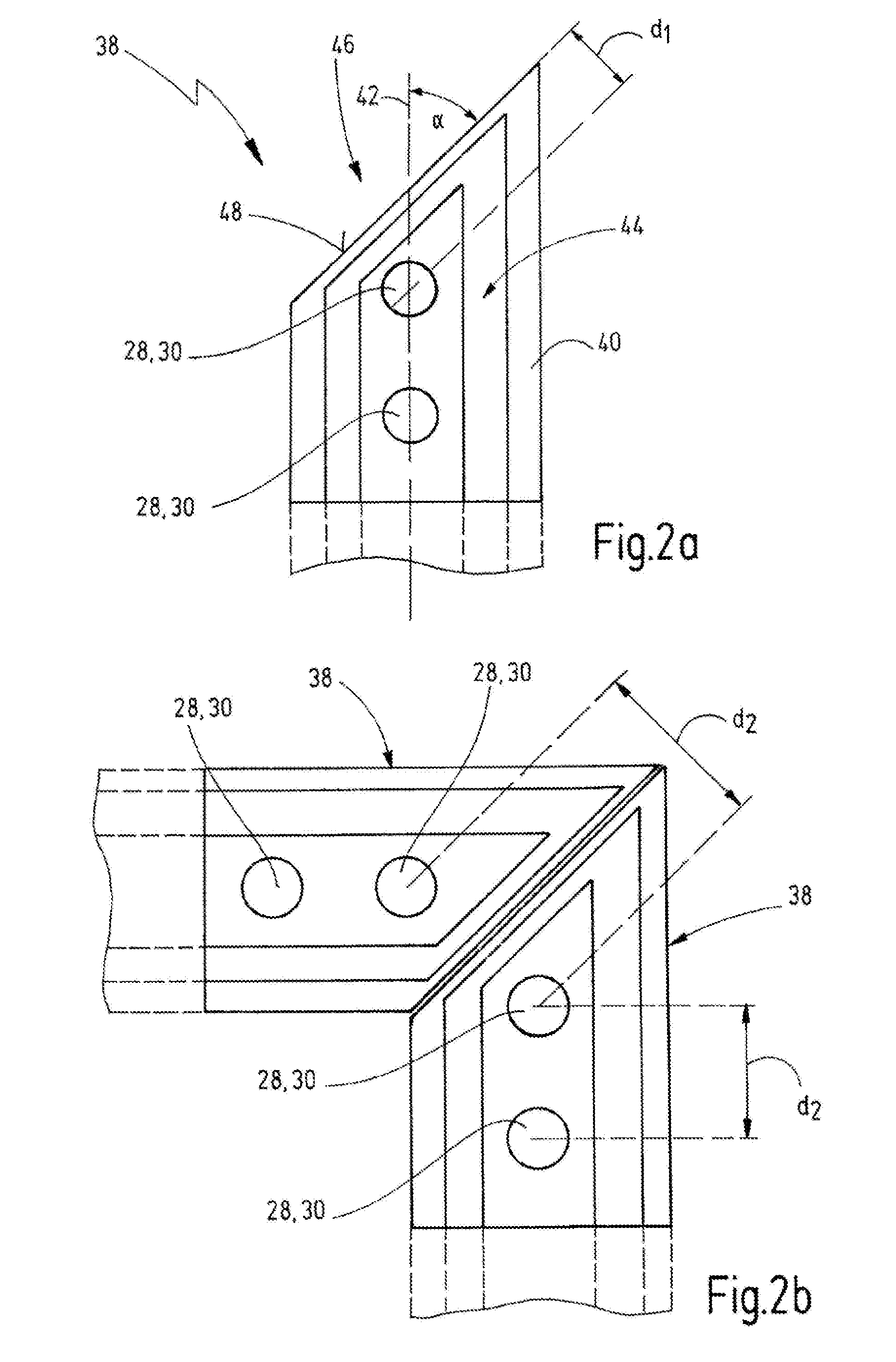
[0047]According to the present disclosure, this is assured by light curtains 24 whose ends have one or more chamfered front surfaces. FIG. 2a shows a light curtain component, which is denoted therein overall by the reference number 38. This light curtain component 38 is preferably configured as an endpiece or so-called end cap which can be mounted on one end of a light curtain rail 24, as is shown in FIG. 5 and will be explained in more detail below. In principle, however, the light curtain component 38 may also be an end of a light curtain rail 26, which is inseparably connected to the rest of the light curtain rail 26.

[0048]The light curtain component 38 has a housing 40, in which the emission and reception elements 28, 30 are respectively arranged. The housing 40 is essentially used as a carrier frame for the emission and reception elements 28, 30, and in this function also acts as mechanical impact protection for the usually sensitive emission and reception elements 28, 30. With...

third embodiment

[0055]In order to avoid a pitch modification, in this third embodiment it is also preferred for the distance d1 between the third planar front surface 52 and the spatially closest emission or reception element 28, 30 to be the same as the distance d1 between this “last” emission or reception element 28, 30 and the planar front surfaces 48″, 50″.

[0056]The greatest possible flexibility is achieved in the embodiment shown in FIG. 4. This is because two light curtain components 38 of this design can then be placed against one another in the widest variety of orientations, without this leading to a modification of the pitch. Three of the possible mutual orientations are shown by way of example in FIGS. 4b-4d. In FIG. 4b, the lower light curtain component 38 is arranged flush with its second planar front surface 50″on the first planar front surface 48″ of the upper light curtain component 38. In FIG. 4c, the two light curtain components 38 respectively meet one another with their third pl...


PUM


Abstract

A light curtain component comprising a housing which extends essentially along a longitudinal direction, and having a plurality of optoelectronic emission or reception elements which are arranged in the housing and are oriented toward an upper side of the housing, and which are separated from one another along the longitudinal direction. The housing comprises, on a front side, a first planar front surface which is arranged at an angle (α) of less than 90°, preferably equal to 45°, with respect to the longitudinal direction. This first planar front surface allows joining two such light curtain components flush with one another in a corner, without undesired formation of dead or blind zones taking place.

Description

CROSS-REFERENCES TO RELATED APPLICATIONS[0001]This application is a continuation of international patent application PCT / EP2014 / 062008, filed on Jun. 10, 2014 designating the U.S., which international patent application has been published in German language and claims priority from German patent application DE 10 2013 106 185.0, filed on Jun. 13, 2013. The entire contents of these priority applications are incorporated herein by reference.BACKGROUND OF THE INVENTION[0002]This disclosure relates to a light curtain component comprising a housing which extends essentially along a longitudinal direction, and having a plurality of optoelectronic emission or reception elements which are arranged in the housing and are oriented toward an upper side of the housing, and which are separated from one another along the longitudinal direction. The present invention furthermore relates to a light curtain comprising such a light curtain component.[0003]Such light curtains are often also referred t...

Claims


Application Information

Patent Timeline
IPC IPC(8): G01V8/20
CPCG01V8/20F16P3/144
Inventor GULDIMANN, DOMINIKLOOP, ROGER
Owner PILZ AUSLANDSBETEILIGUNGEN
Why Eureka
Try Eureka