Methods for manufacturing a spar cap for a wind turbine rotor blade

a technology for wind turbines and rotor blades, which is applied in the manufacture of final products, machines/engines, other domestic articles, etc., can solve the problems of parts delaminate and defects in the resulting parts, and achieve the effect of reducing the stress concentration

Inactive Publication Date: 2016-05-26
GENERAL ELECTRIC CO
View PDF4 Cites 24 Cited by
  • Summary
  • Abstract
  • Description
  • Claims
  • Application Information

AI Technical Summary

Benefits of technology

The patent describes a method for making a rotor blade component by joining multiple pultrusions together. The pultrusions are cured and then bonded together using an adhesive or similar material. This reduces stress concentration at the ends of the pultrusions. The fibers used can be glass or carbon, and the resin material can be polyester, polyurethane, or similar. The technical effect is a stronger and more durable rotor blade component.

Problems solved by technology

The technical problem addressed in this patent text is the need for an improved pultruded spar cap that addresses areas of local stress concentration and vacuum bag bridging issues that can lead to defects in the resulting part. Specifically, a spar cap constructed with one or more pultrusions having tapered ends would be advantageous.

Method used


Image

  • Methods for manufacturing a spar cap for a wind turbine rotor blade
  • Methods for manufacturing a spar cap for a wind turbine rotor blade
  • Methods for manufacturing a spar cap for a wind turbine rotor blade

Examples


Embodiment Construction

[0022]Reference now will be made in detail to embodiments of the invention, one or more examples of which are illustrated in the drawings. Each example is provided by way of explanation of the invention, not limitation of the invention. In fact, it will be apparent to those skilled in the art that various modifications and variations can be made in the present invention without departing from the scope or spirit of the invention. For instance, features illustrated or described as part of one embodiment can be used with another embodiment to yield a still further embodiment. Thus, it is intended that the present invention covers such modifications and variations as come within the scope of the appended claims and their equivalents.

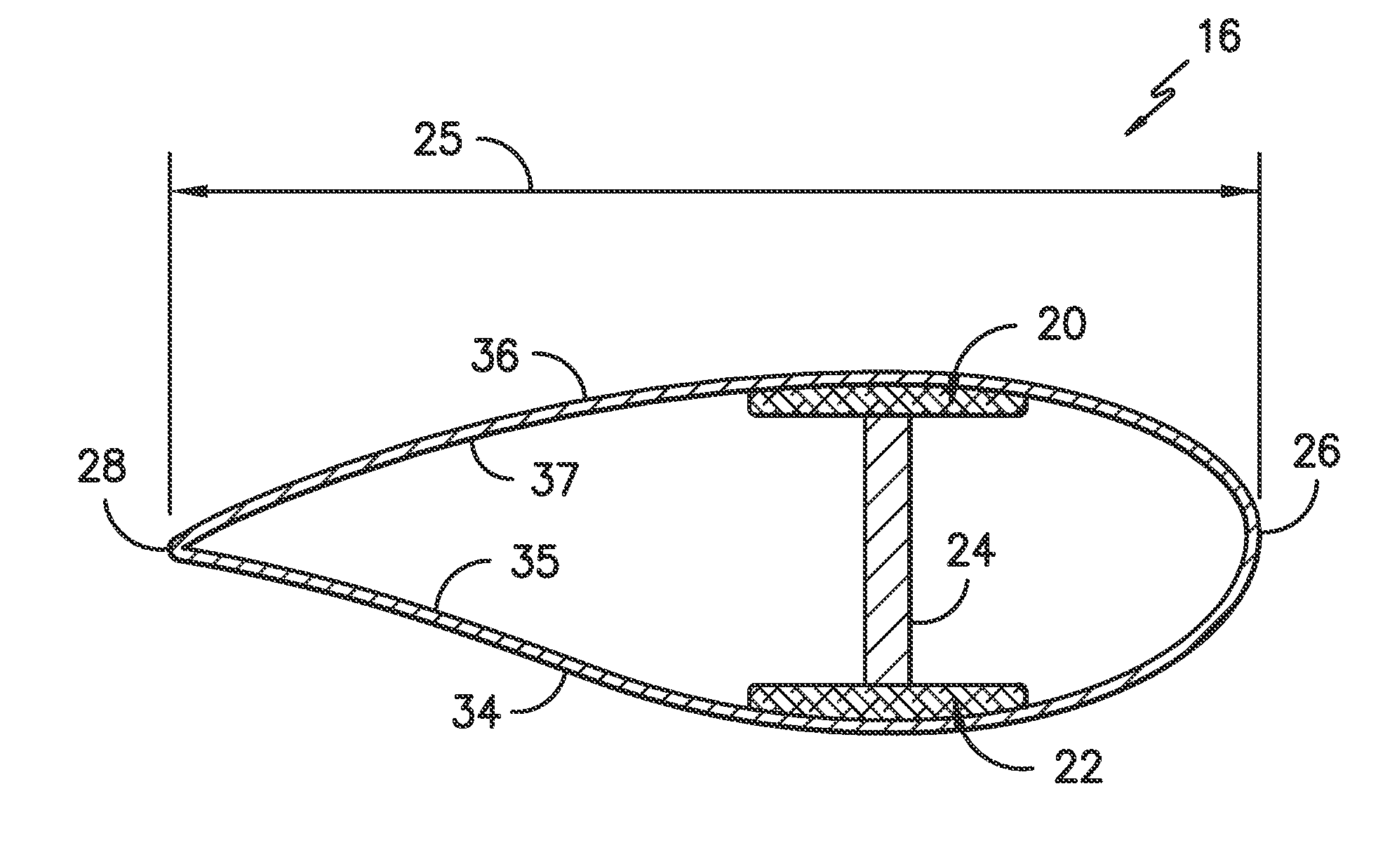
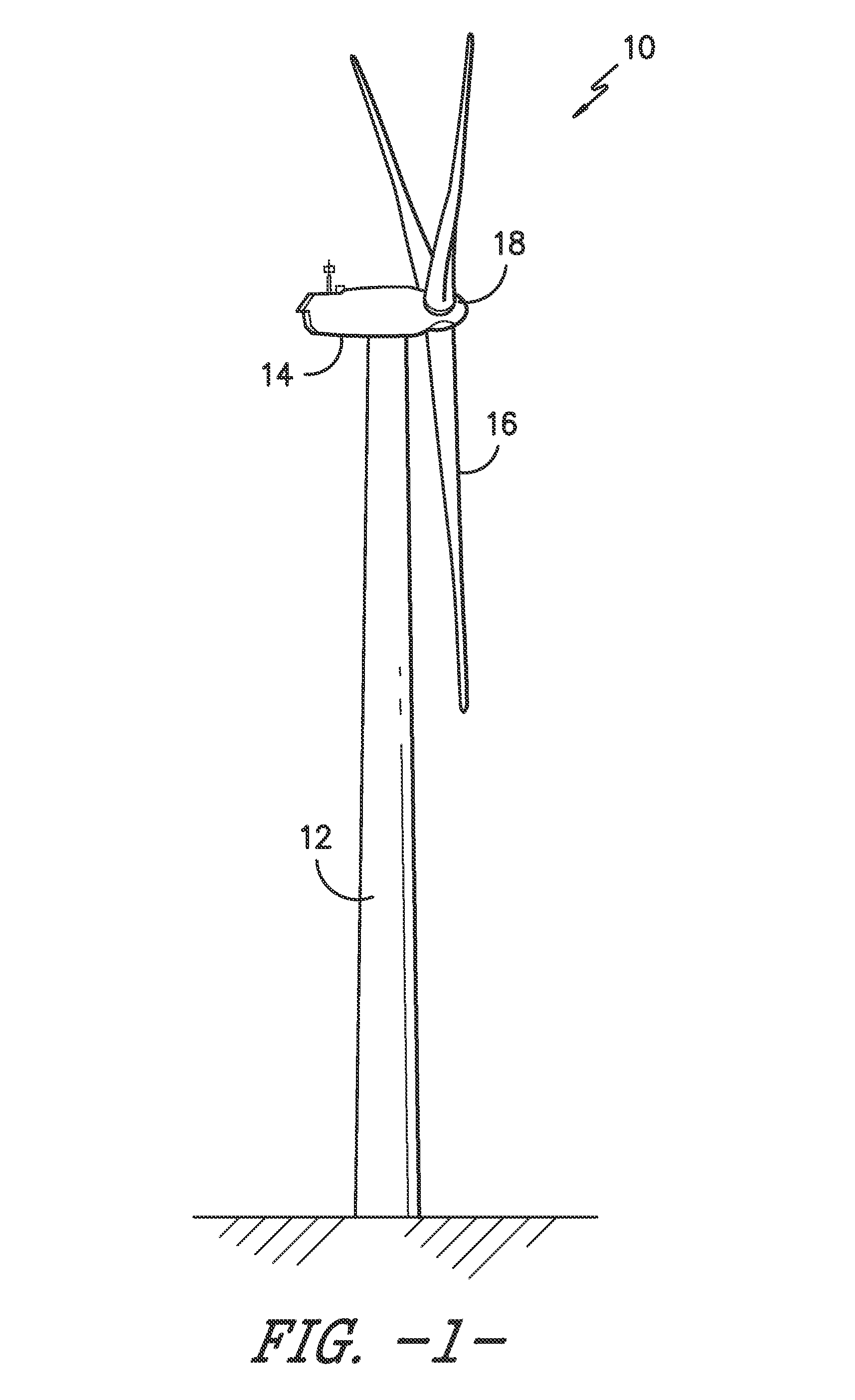
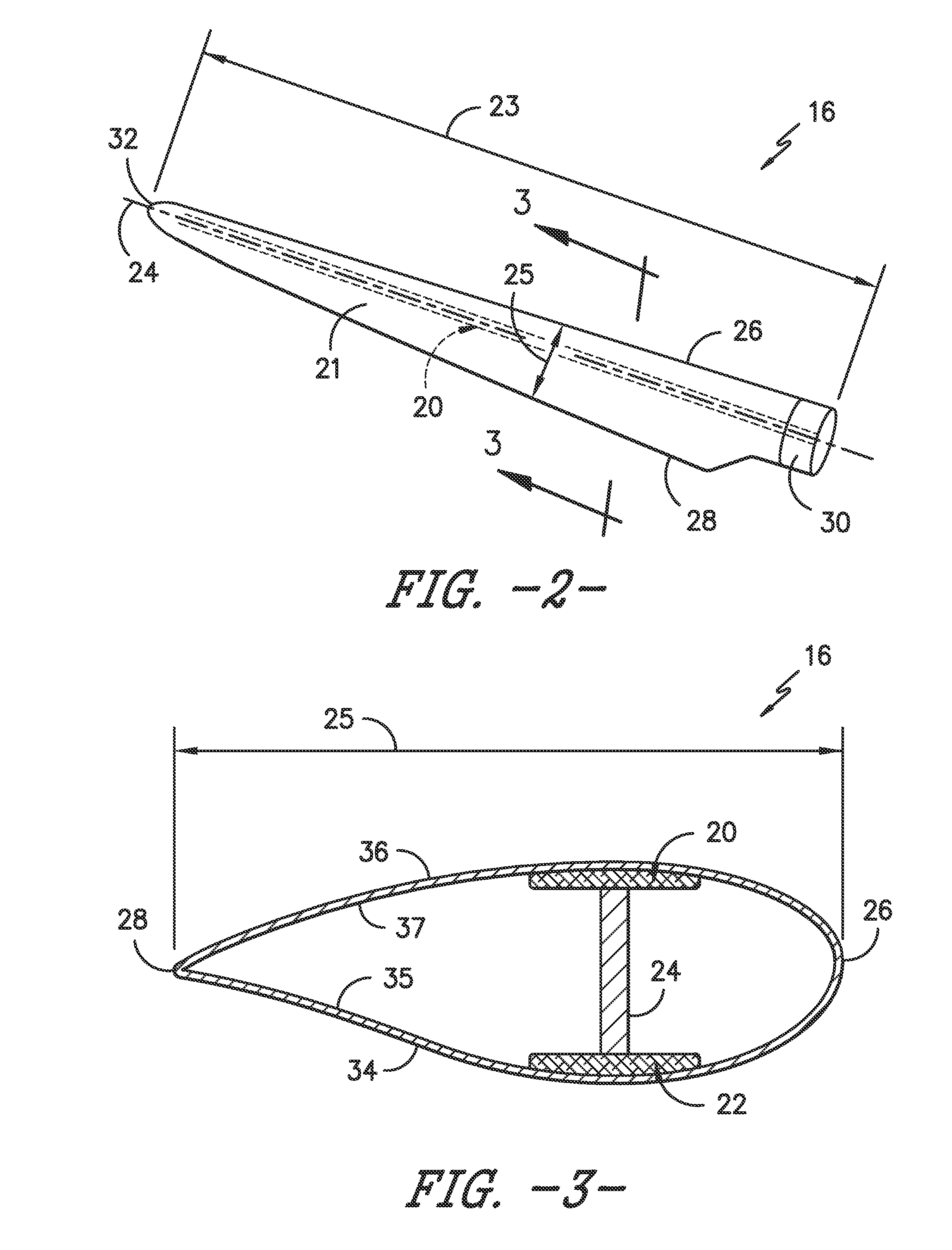
[0023]Generally, the present subject matter is directed to a pultruded spar cap of a rotor blade of a wind turbine and methods of manufacturing same. For example, in one embodiment, the method includes providing a plurality of pultrusions and tapering at le...


PUM

PropertyMeasurementUnit
Angleaaaaaaaaaa
Angleaaaaaaaaaa
Angleaaaaaaaaaa

Abstract

Methods of manufacturing spar caps for a rotor blade of a wind turbine are disclosed. The method includes providing a plurality of pultrusions constructed of one or more fibers or fiber bundles cured via a resin material. Another step includes tapering the ends of the pultrusions at a predetermined angle. The method also includes arranging the tapered pultrusions in a mold of the spar cap. The method also includes joining the plurality of pultrusions together so as to form the spar cap.

Description


Claims


Application Information

Patent Timeline
Owner GENERAL ELECTRIC CO
Why Eureka
Try Eureka