Assembled battery and manufacturing method of assembled battery

Active Publication Date: 2016-05-26
TOYOTA JIDOSHA KK
View PDF3 Cites 14 Cited by
  • Summary
  • Abstract
  • Description
  • Claims
  • Application Information

AI Technical Summary

Benefits of technology

[0031]The above manufacturing method uses a holder in which the cell hold portion is configured such that the inside diameter of the first open end, which is an open end of the holding hole on the first-surface side, is made smaller than the inside diameter of the second open end, which is an open end of the holding hole on the second-surface side. Since the inside diameter (a diameter) of the second open end is made larger than the inside diameter (a diameter) of the first open end as such, when the adhesive is injected into the gap from the second-surface side of the cell hold portion in a state where the second surface of the cell hold portion is directed upward (the first surface is directed downward) in the adhesive injection step, the adhesive easily comes inside the gap. Further, since the inside diameter of the first open end is smaller than the inside diameter of the second open end, when the adhesive is injected from the second-surface side of the cell hold portion in the adhesive injection step, the adhesive thus injected from the second-surface side is hard to drop from the first-surface side.
[0032]Besides, that inner peripheral surface of the cell hold portion which constitutes the holding hole includes the tapered surface having an inside diameter that is increased toward the second-surface side from the first-surface side. Because of this, the adhesive injected from the second-surface side easily flows toward the first-surface side along the tapered surface, which allows the adhesive to be easily filled into the gap. Hereby, the adhesive can be sufficiently filled into the gap.

Problems solved by technology

On this account, when a vibration or an impact is applied to the battery module, the unit cell moves inside the holder in a radial direction and an axis direction (a height direction) of the unit cell, which might cause rattling between the unit cell and the holder and between the unit cell and each of the positive-electrode spacer and the negative-electrode spacer.

Method used


Image

  • Assembled battery and manufacturing method of assembled
battery
  • Assembled battery and manufacturing method of assembled
battery
  • Assembled battery and manufacturing method of assembled
battery

Examples


embodiment 1

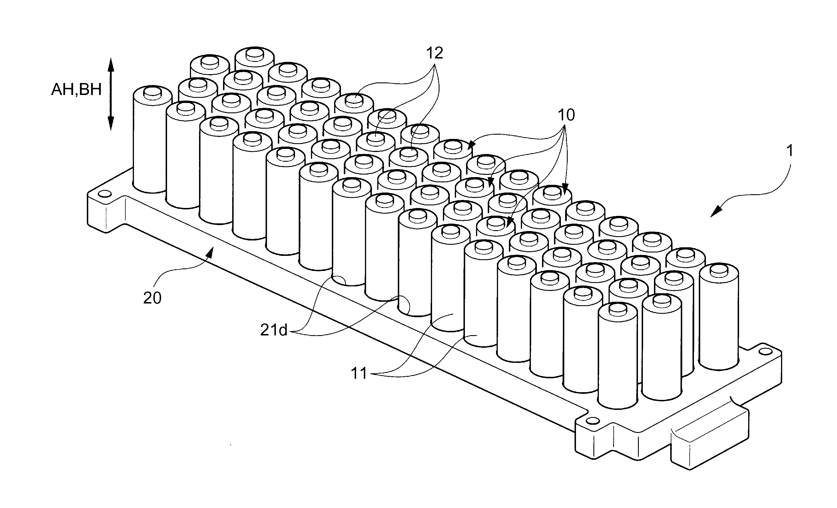
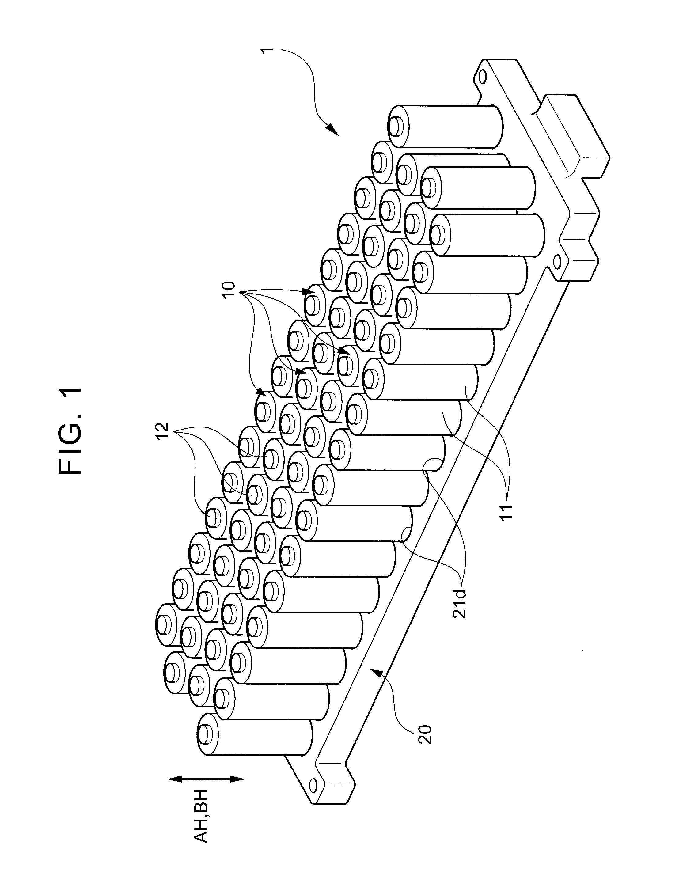
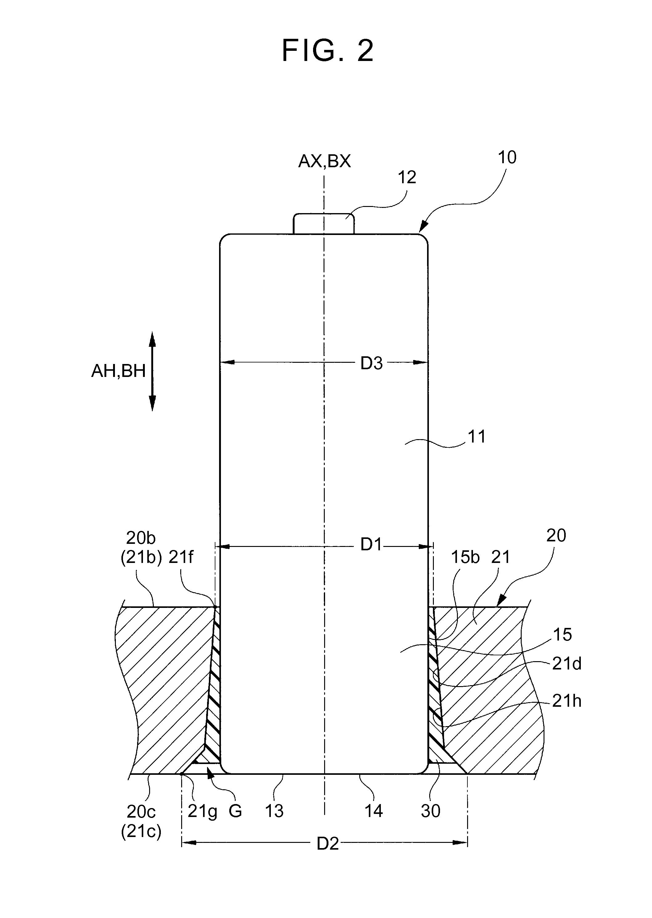
[0056]Note that, in Embodiment 1, an outside diameter D3 of the cell 10 is made smaller than a minimum inside diameter (more specifically, an inside diameter D1 of a first open end 21f, which is an open end of the holding hole 21d on a first-surface-21b side) of the holding hole 21d, as illustrated in FIG. 2. This allows the cell 10 to be inserted into the holding hole 21d. More specifically, part of the cell 10 is inserted into the holding hole 21d.

[0057]Further, as illustrated in FIG. 2, the assembled battery 1 of Embodiment 1 includes an adhesive 30 injected and solidified in a gap G between an outer peripheral surface 15b of that part (referred to as a held portion 15) of the cell 10 which is placed inside the holding hole 21d and that inner peripheral surface 21h of the cell hold portion 21 which constitutes the holding hole 21d. Hereby, each of the cells 10 is fixed to the holder 20 in a state where the each of the cells 10 is held by each of the cell hold portions 21 via the...

embodiment 2

[0077]The assembled battery 101 of Embodiment 2 includes one resin sheet 40 provided so as to make contact with first surfaces 21b of a plurality of cell hold portions 21 (one resin sheet 40 adhered to the first surfaces 21b). In other words, one resin sheet is provided on a first surface 20b of a holder 20 (one resin sheet is adhered to the first surface 20b). As illustrated in FIG. 11, the resin sheet 40 has cylindrical through holes 41 penetrating therethrough. More specifically, the same number of through holes 41 as the number of holding holes 21d formed in the holder 20 is formed in the resin sheet 40. Moreover, each of the through holes 41 has an inside diameter D4 (a diameter D4) which is smaller than an inside diameter (more specifically, an inside diameter D1 of a first open end 21f, which is an open end of the holding hole 21d on a first-surface-21b side) of the holding hole 21d of the cell hold portion 21 and which is smaller than an outside diameter D3 of the cell 10 (s...


PUM

PropertyMeasurementUnit
viscosityaaaaaaaaaa
diameter D2aaaaaaaaaa

Abstract

An assembled battery includes: a holder including a plurality of cell hold portions each having a first surface and a second surface facing an opposite side to the first surface and each having a holding hole, which is a hole penetrating through between the first surface and the second surface, and a connection portion that connects the plurality of cell hold portions to each other; a plurality of cells each having an outside diameter smaller than an inside diameter of the holding hole and inserted into the holding hole of each of the plurality of cell hold portions; and an adhesive provided so as to be solidified in a gap between an outer peripheral surface of a part of the cell which is placed inside the holding hole and an inner peripheral surface of the cell hold portion which constitutes the holding hole.

Description

INCORPORATION BY REFERENCE[0001]The disclosure of Japanese Patent Application No. 2014-237508 filed on Nov. 25, 2014 including the specification, drawings and abstract is incorporated herein by reference in its entirety.BACKGROUND OF THE INVENTION[0002]1. Field of the Invention[0003]The present invention relates to an assembled battery and a manufacturing method of an assembled battery.[0004]2. Description of Related Art[0005]There is an assembled battery configured such that a plurality of cells is accommodated in a holder. For example, Japanese Patent Application Publication No. 2013-196810 (JP 2013-196810 A) describes a battery module configured such that a plurality of cylindrical unit cells is accommodated in respective cylindrical holders, and further, upper parts of these holders are fixed by a positive-electrode spacer and lower parts of the holders are fixed by a negative-electrode spacer.SUMMARY OF THE INVENTION[0006]However, in the battery module described in JP 2013-1968...

Claims


Application Information

Patent Timeline
Patent Type & Authority Applications(United States)
IPC IPC(8): H01M2/10H01M50/213H01M50/224H01M50/244H01M50/264
CPCH01M2/1016H01M2/1077H01M2/105H01M10/0404H01M50/24H01M50/244H01M50/224H01M50/264H01M50/213Y02E60/10Y02P70/50
Inventor MORIMITSU, TAKATOSHIOKURA, TOSHINORI
Owner TOYOTA JIDOSHA KK
Why Eureka
Try Eureka