
Portable Quick Fit Filter Assembly

a filter assembly and quick-fit technology, applied in the direction of filtration separation, manufacturing tools, separation processes, etc., can solve the problems of difficult to change the filter inside the housing, the existing filter assembly is difficult to easily disassemble and assemble, and the present filter assembly is also difficult to bring along, so as to achieve the effect of more retention tim

Active Publication Date: 2012-12-20
AYRO CORP
View PDF2 Cites 2 Cited by
  • Summary
  • Abstract
  • Description
  • Claims
  • Application Information

AI Technical Summary

Benefits of technology

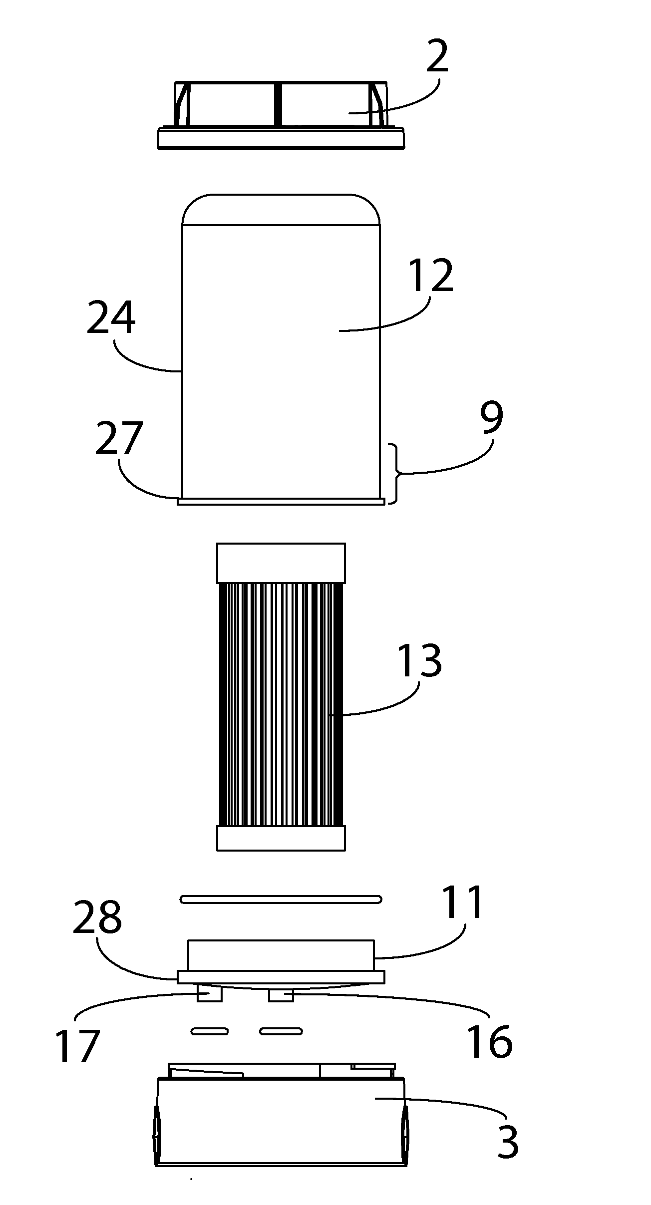
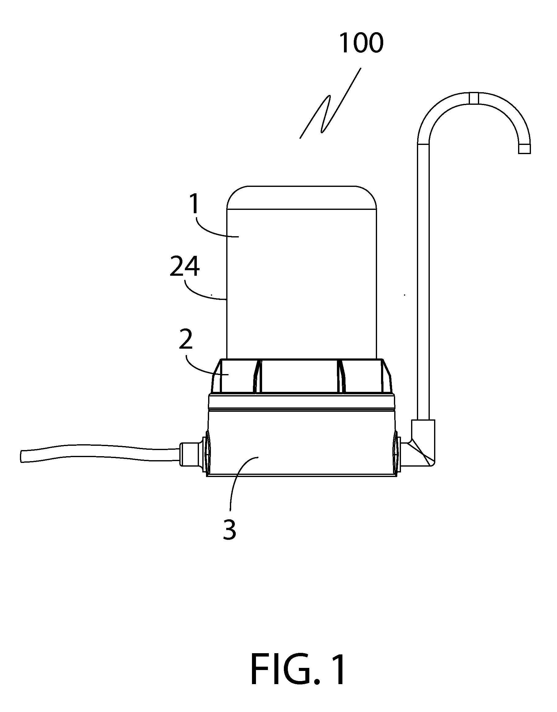
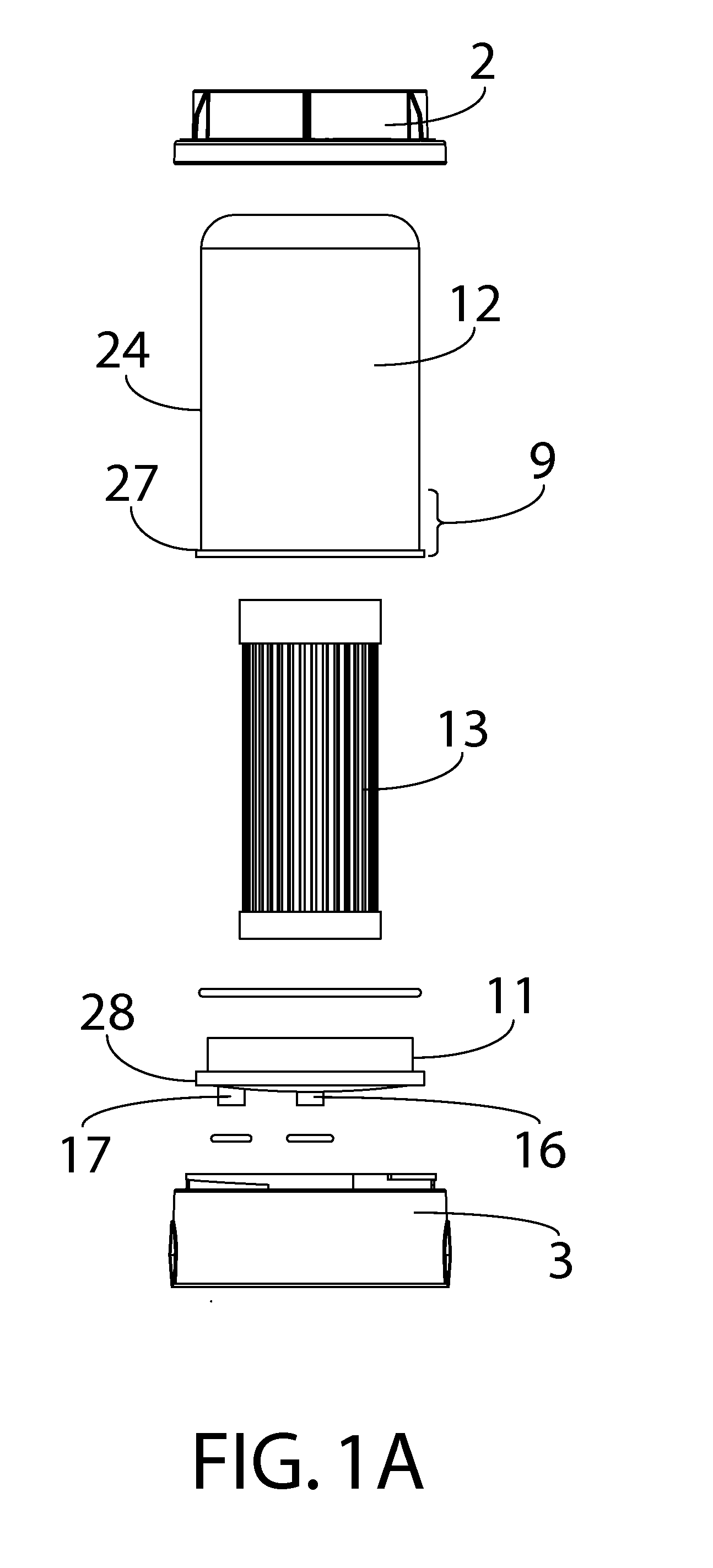
[0006]A portable counter top fluid filter assembly, comprises a filter housing having a bottom cover and a hollow domelike cover enveloping a filter attaching to the bottom cover an inlet and an outlet for the fluid; a filter base having a main body including a cylindrical trough-like top section having a flat interior surface, an inlet port and an outlet port, an elevated flat ring at the flat interior surface periphery, an upright protruding rim extending from the flat interior surface of the filter base proximal to the periphery, the protruding rim having female receptors on an outside surface of the rim recessed from the main body of the filter base, a bottom section beneath the trough-like top section having a flat bottom outer surface, an inlet entry port connecting to a fluid source and communicating with the inlet port at the trough-like top section, the inlet port, in turn, connecting to the inlet of the filter housing, an outlet exit port connecting to a fluid delivery device and communicating with the outlet port at the trough-like top section, the outlet port connecting, in turn, with the outlet of the filter housing; and, a filter locking ring locking the filter housing to the filter base having a flat ring base, an upright wall touching a side outside surface of the filter housing when introduced through and around the filter housing, the upright wall extending from a peripheral tip at an interior border of the flat ring base and recessed from the exterior peripheral tip of the flat ring base, a pin like protrusion at an inside surface of the flat ring base inserting into the female receptor of the filter base when the filter locking ring locks the filter housing to the filter base. The upright protruding rim of the filter base surrounds an outside bottom portion of the filter housing when the filter housing is engaged with the filter base. The filter inside the filter housing may be permanently housed, that is, not replaceable and the bottom cover and the domelike cover of the filter housing are permanently attached to each other. To be able to control the residence time of contact between the filter and the fluid, the inlet and outlet at the bottom cover can be made to be replaceable and its inside diameter varied. For example, with the same inlet flow rate of the liquid into the filter housing, an outlet with a smaller inside diameter will provide more retention time for the liquid to contact the filter. Aside from matching the inlet and outlet at the filter housing with those at the filter base, a nib at the filter base and a matching indentation at the filter housing and vice versa may be used to further position the filter housing with the filter base. The bottom section of the filter base may be hollow or solid. The female receptor on the filter base may be designed as a tract where the pin like protrusion at the filter locking ring slips into and situates at an end of the tract when the filter locking ring connects with the filter base, thereby locking the filter base to the filter housing. It is recommended to have a tapered tract for ease of entry by the pin without sacrificing the snugness needed to keep the pin at the end of the tract. A notation on the direction of the twisting motion to lock the filter base with the filter housing may be printed, embossed or etched at a top surface of the flat ring base. A felt mat be placed on the inside surface of the bottom cover of the filter housing to prevent filter particles from mixing with or contaminating the filtered effluent fluid flowing from the filter assembly. A plurality of protruding lines on an inside surface of the upright cylindrical wall of the filter locking ring provide clearance between the filter housing and the upright cylindrical wall while the plurality of protruding lines on an outside surface of the upright cylindrical wall of the filter locking ring provide a grip when handling the filter locking ring.

Problems solved by technology

Existing filter assemblies are hard to easily disassemble and assemble, often needing a wrench or a screw driver to open or tightly close the housing containing the filter to prevent leakage.
This has made it difficult to change the filter inside the housing especially when minerals deposit around the area where the body of the housing connects with the cover.
Present filter assemblies are also difficult to bring along when traveling.
Further, it is lightweight, making it easy to transport the filter assembly from one fluid or liquid outlet to another requiring only accessories like an adapter if the outlet port of the fluid source like a faucet is not of a standard sized threaded opening.

Method used


Image

  • Portable Quick Fit Filter Assembly
  • Portable Quick Fit Filter Assembly
  • Portable Quick Fit Filter Assembly

Examples


Embodiment Construction

[0026]The detailed description represented herein is not intended to represent the only way or the only embodiment in which the claimed invention may be practiced. The description herein is provided merely as an example or examples or illustrations of the claimed invention and should not be construed as the only way or as preferred or advantageous over other embodiments or means of practicing the invention. A filter assembly constructed the same or similarly to those illustrated and described herein is within the scope of this invention. The detailed description includes specific details to provide a thorough understanding of the claimed invention and it is apparent to those skilled in the art that the claimed invention may be practiced without these specific details. In some instances, well known structures and devices or structures that do not form a part of the invention may be lightly lined and / or shaded in order to avoid obscuring the main concepts of the invention.

[0027]The us...


PUM

PropertyMeasurementUnit
diametersaaaaaaaaaa
areaaaaaaaaaaa
diameteraaaaaaaaaa

Abstract

A portable table top filter assembly including a filter housing enveloping a filter having an inlet and an outlet for the fluid; a flat bottomed filter base having an inlet port and an outlet port communicating with the inlet and outlet of the filter housing and a protruding rim having connectors on an outside surface of the rim recessed from the main body of the filter base, an inlet entry port at a bottom section of the filter base for connecting to a fluid source and communicating with the inlet port of the filter base, an outlet exit port connecting to a fluid delivery device and communicating with the outlet port of the filter base; and, a filter locking ring locking the filter housing to the filter base when a connector at the filter locking ring connects with the connector at the filter base.

Description

[0001]This invention relates to a portable table top fluid filter assembly that is easy to assemble and fits into an existing outlet.BACKGROUND[0002]Existing filter assemblies are hard to easily disassemble and assemble, often needing a wrench or a screw driver to open or tightly close the housing containing the filter to prevent leakage. This has made it difficult to change the filter inside the housing especially when minerals deposit around the area where the body of the housing connects with the cover. The filter assembly herein does not require any tools to open and is very simple in construction to enable one to install or change the filter with very little downtime. Present filter assemblies are also difficult to bring along when traveling. There are some countries where the ability to filter the local water would be recommended especially to those with a weak immune system. Further, it is lightweight, making it easy to transport the filter assembly from one fluid or liquid o...

Claims


Application Information

Patent Timeline
Patent Type & Authority Applications(United States)
IPC IPC(8): B01D35/30B23P11/00B01D35/02
CPCB01D2201/4023B01D2201/4015B01D29/15Y10T29/49826B01D29/96B01D2201/302B01D35/30
Inventor TSENG, WEI CHENG
Owner AYRO CORP
Learn More