Fluid separator

Inactive Publication Date: 2006-12-21
ZEBRA SKIMMERS CORP
View PDF13 Cites 3 Cited by
  • Summary
  • Abstract
  • Description
  • Claims
  • Application Information

AI Technical Summary

Benefits of technology

[0014] According to a further aspect, the strip comprises a tube having a generally circular cross section. According to a particular aspect, the apparatus can include a scraping annulus through which the successive portions of the strip pass, the scraping annulus having an inside diameter sufficiently small that the first fluid collected on the successive portions of the strip is removed therefrom as the successive portions of the strip pass through the scraping annulus. Additionally, the scraping annulus can be generally secured against movement with the strip as a result of the passage of the successive portions of the strip through the scraping annulus. The scraping annulus can be located so that the first fluid is removed f

Problems solved by technology

Aqueous coolants of this type are fairly expensive.
These lubricating oils, typically referred to as “tramp oil,” eventually contribute to bacterial growth within the tank holding the aqueous coolant, resulting in a foul odor and reducing the useful life of the aqueous coolant.
Moreover, due to environmental considerations, the oil-contaminated aqueous coolant must be treated as a hazardous waste and its disposal represents an environmental and economic concern.
However, conventional tube skimmers frequently suffer binding and jamming problems with the tube.

Method used


Image

  • Fluid separator
  • Fluid separator
  • Fluid separator

Examples


first embodiment

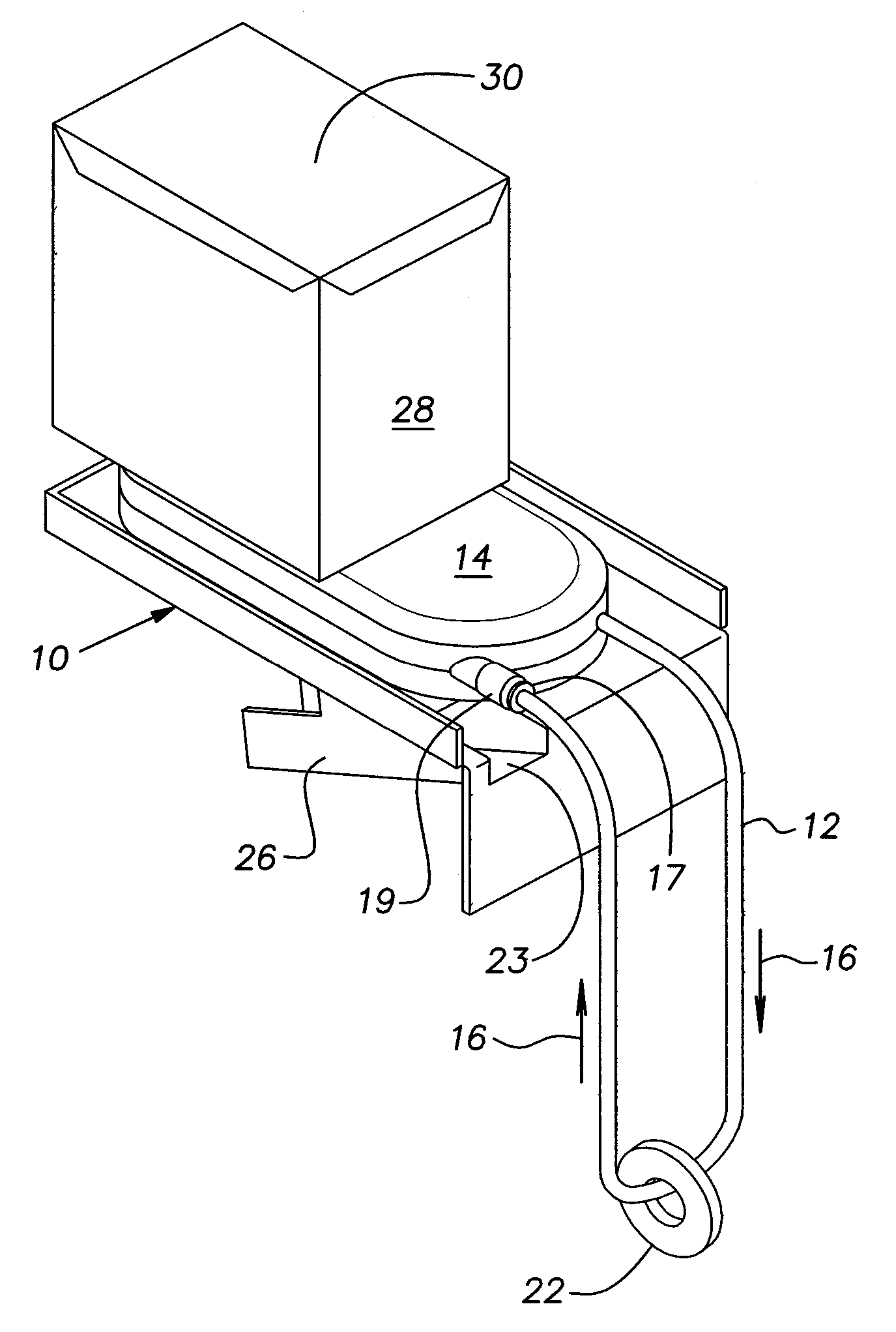
[0025] Turning to the drawings, there is shown in FIG. 1 an apparatus for separating a first fluid from a mixture of fluids. The illustrated apparatus comprises a tube skimmer that incorporates the features of the present invention. The tube skimmer of the illustrated embodiment includes a support platform 10 which can be mounted to a process fluid tank, or container (not shown), in which the mixture of fluids is held or any other suitable structure adjacent the process fluid tank. In a machining operation, the process fluid tank typically contains a process fluid, such as a coolant, and a tramp oil that is substantially immiscible with respect to and floats on top of the coolant. It will be understood that the apparatus of the invention is not limited to use in separating a tramp oil from a coolant in a machining operation but has general application to circumstances where a first fluid is separated from a mixture of fluids in a container, the first fluid being substantially immisc...

second embodiment

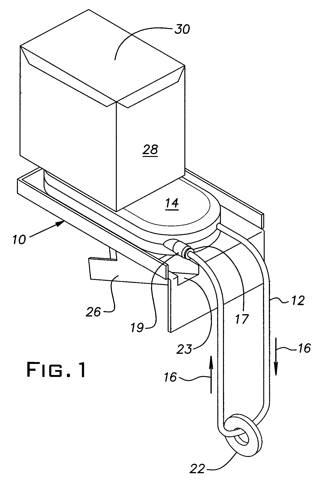
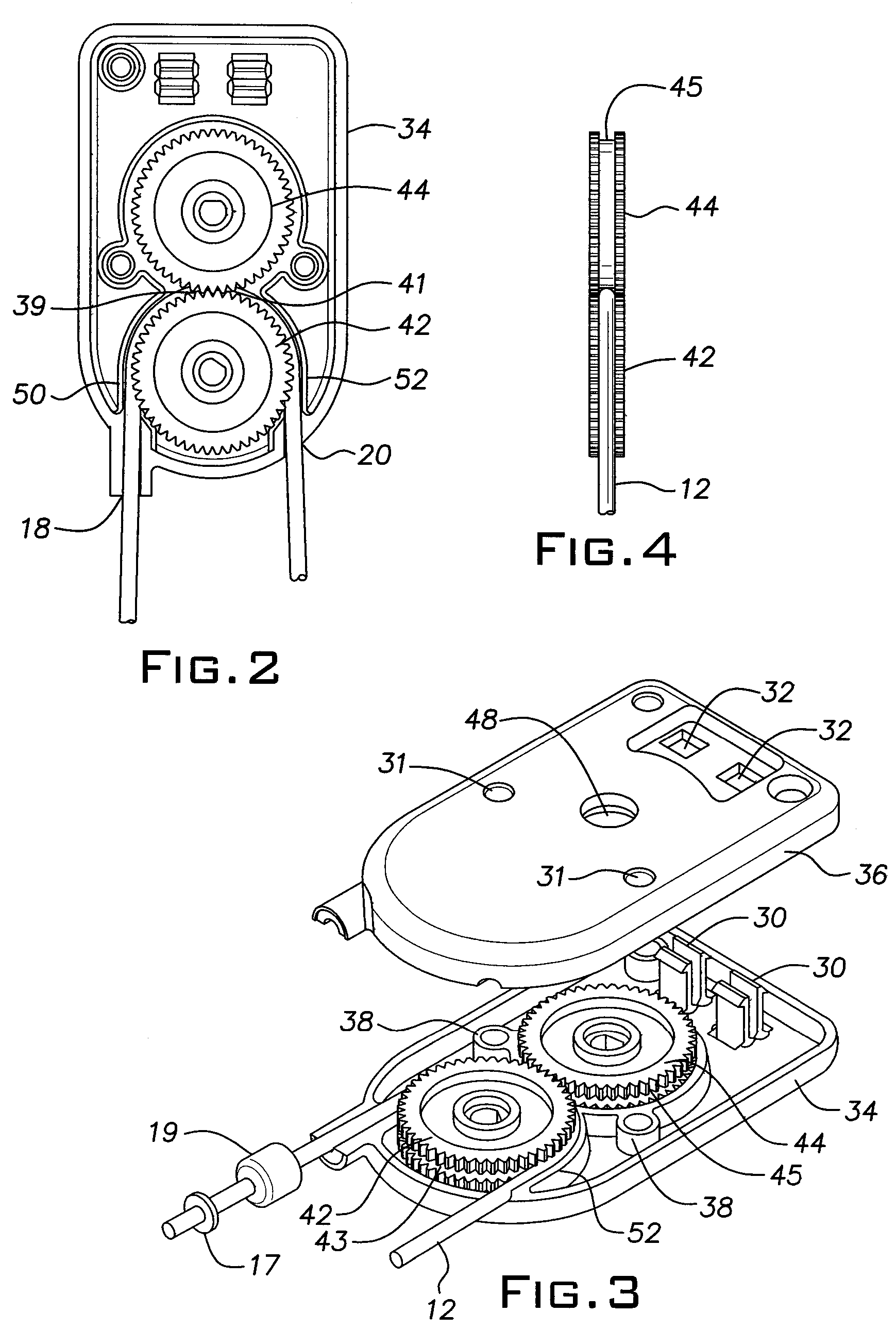
[0037] Referring now to FIGS. 5 and 6, the invention is illustrated. Specifically, FIG. 5 illustrates a gearbox arrangement that can be used in place of the gearbox 14 shown in FIGS. 1 through 4. The gearbox of FIG. 5, which is shown with the upper housing portion 36 of the gearbox removed, includes all the elements of the gear box of FIGS. 1 through 4 including the circular rotating gears 42 and 44, shown in section in FIG. 5, and the description of the gearbox 14 and its operation set forth above with reference to FIGS. 1 through 4 is equally applicable to the gearbox of FIG. 5. However, the gearbox of FIG. 5 includes, in addition, a guiding element 62 located at the exit location 41 for directing the strip or tube 12 away from engagement with the cooperating surface 45 of the first advancing member or first circular rotating gear 44 and into continued engagement with the cooperating surface 43 of the second advancing member or second circular rotating gear 42 at the exit location...


PUM

PropertyMeasurementUnit
Forceaaaaaaaaaa
Diameteraaaaaaaaaa
Flexibilityaaaaaaaaaa

Abstract

An apparatus for separating a first fluid from a mixture of fluids in a container, the first fluid being substantially immiscible with respect to one or more other fluids in the mixture comprises an endless strip of material having an affinity for the first fluid, a pair of advancing members for advancing successive portions of the strip into and out of contact with the first fluid and a means for maintaining the successive portions of the strip in contact with the first fluid as the successive portions of the strip are sequentially advanced. The pair of advancing members have cooperating surfaces that positively engage the strip with sufficient force so that movement of the advancing members relative to one another sequentially advances successive portions of the strip. A guiding element directs the strip away from engagement with the cooperating surface of one of the advancing members at the location where the strip is released from positive engagement with the advancing members

Description

[0001] This application is a continuation-in part of U.S. patent application Ser. No. 10 / 943,730, filed Sep. 17, 2004, which claims the benefit of U.S. Provisional Application No. 60 / 503,781, filed Sep. 19, 2003.FIELD OF THE INVENTION [0002] The present invention relates generally to an apparatus for separating fluids and, more specifically, to an apparatus for removing tramp oil from coolants used in machining centers. BACKGROUND OF THE INVENTION [0003] There are a variety of instances where it is desired to separate a fluid from a mixture of fluids. For example, in many machining operations, an aqueous coolant is sprayed or flowed at the location where a cutting tool engages the workpiece for lubrication and cooling purposes. The coolant is then collected in a tank and recycled for continuous use for as long as possible. Aqueous coolants of this type are fairly expensive. Consequently, it is advantageous to maintain such coolants in a usable condition for as long as possible. Typi...

Claims


Application Information

Patent Timeline
IPC IPC(8): B23D25/02B01D17/02C02F1/40
CPCB01D17/0202B01D17/0214Y10S210/923Y10T83/4827
Inventor DAVIDIAN, STEVEN
Owner ZEBRA SKIMMERS CORP
Why Eureka
Try Eureka