
Gas circulation type laser oscillator

Active Publication Date: 2015-11-19
FANUC CORP
View PDF2 Cites 0 Cited by
  • Summary
  • Abstract
  • Description
  • Claims
  • Application Information

AI Technical Summary

Benefits of technology

The present invention is related to a gas circulation type laser oscillator which can prevent dust mixed in the laser gas from adhering to the optical components. The technical effects of the invention include the use of blocking members with hollow tubular forms and gaps between the outer and inner surfaces, the provision of a discharge tube with a reduced flow rate of laser gas towards the optical components, the increase in the flow rate of laser gas flowing into the blower piping rather than through the through holes of the end walls, the prevention of overheating of the blocking members, the provision of both a feed source and an exhaust pump connected to the middle of the blower piping, the use of blocking members with high heat conductivity, and the provision of through holes, optical components, and blocking members on both sides in the extension direction of the discharge tube.

Problems solved by technology

Furthermore, an oxidation reaction of ozone which is produced during excitation discharge of the mixed gas may also cause formation of various oxides.
If these foreign matters adhere to a partial reflector or total reflector or other optical components, the output power of the laser will reduce, and it may create a need to clean or replace the optical components.
However, according to the structure of the laser oscillator of JP2003-110171A, foreign matter which had adhered to the inside wall of the feed piping of the laser gas may be discharged near the reflection mirrors, and therefore the reflection mirrors may be contaminated further due to that foreign matter.
However, the laser oscillator of JPH05-102575A can only prevent mixing of the foreign matter in the heat exchanger into the blower path during the time of assembly, and cannot prevent contamination of the optical components due to foreign matter which is produced due to excitation discharge of the laser gas.

Method used


Image

  • Gas circulation type laser oscillator
  • Gas circulation type laser oscillator
  • Gas circulation type laser oscillator

Examples


Embodiment Construction

[0021]Below, embodiments of the present invention will be explained in detail with reference to the drawings. Note that the following explanation does not limit the technical scope of the inventions which are described in the claims or the meaning of terms etc.

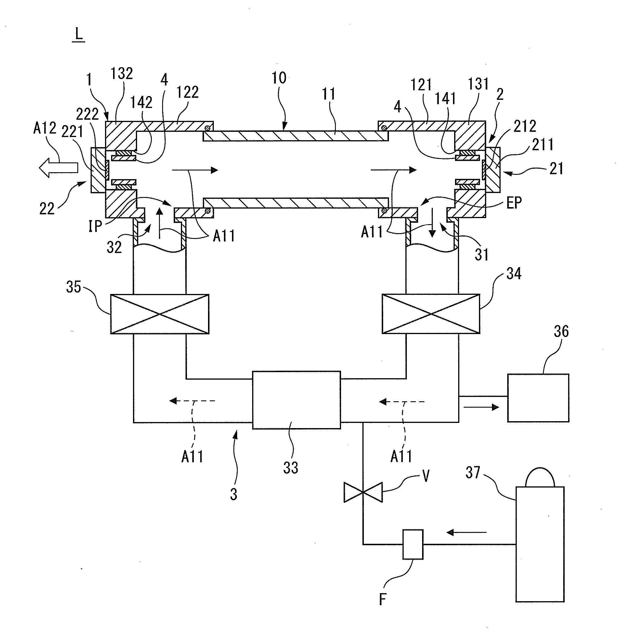
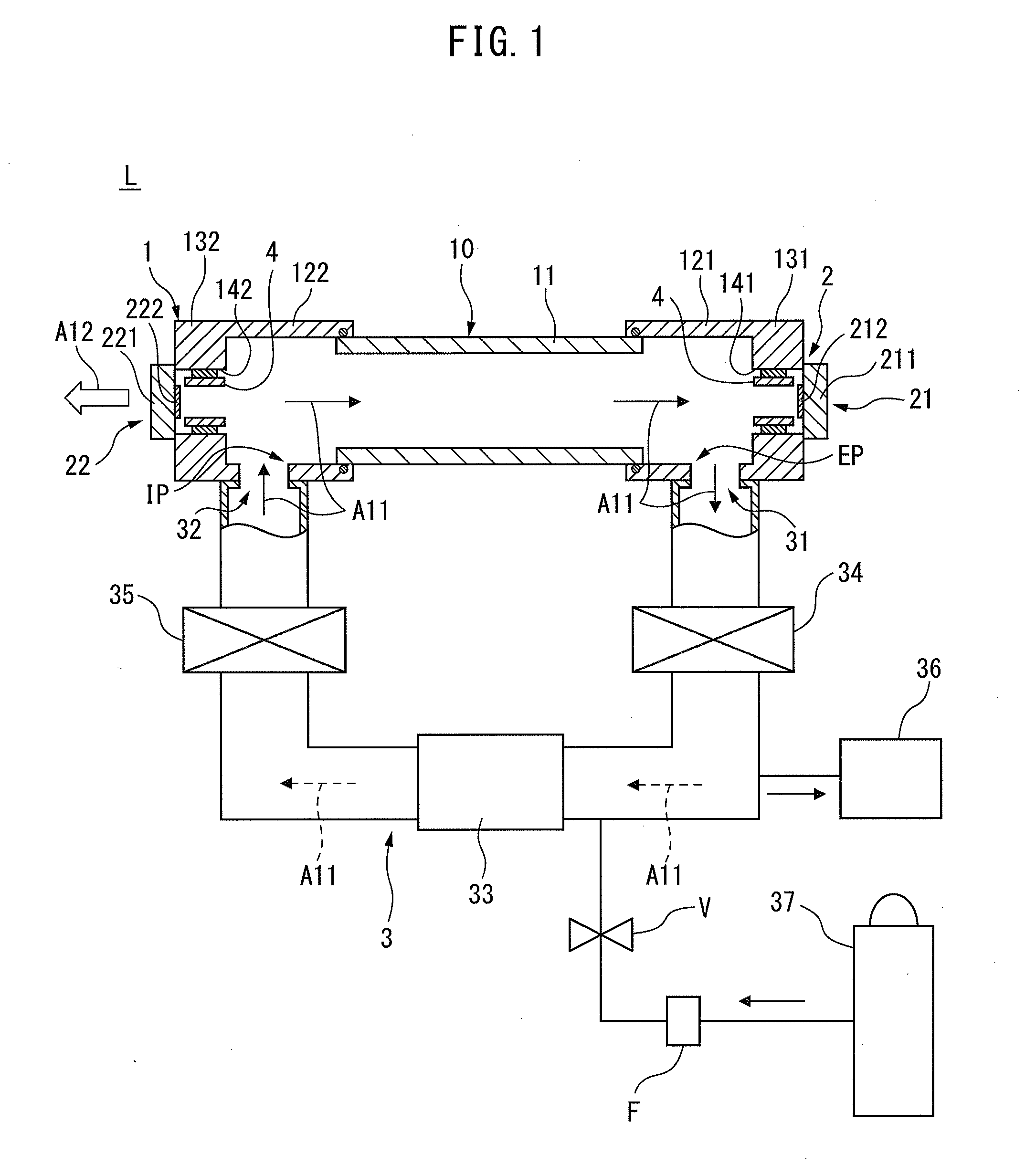
[0022]Referring to FIG. 1 to FIG. 6, a laser oscillator of one embodiment of the present invention will be explained. The laser oscillator of the present embodiment is a gas circulation type laser oscillator which is configured to generate laser by circulating laser gas mainly comprised of carbon dioxide gas, nitrogen gas, and helium gas at a high speed, and causing high frequency electric discharge in the laser gas to excite the carbon dioxide gas. The laser oscillator of the present embodiment can be mounted in a laser processing machine which is mainly used for cutting, welding, etc. of metal materials and plastic materials etc. FIG. 1 is a longitudinal cross-sectional view of an illustrative laser oscillator L of the prese...


PUM


Abstract

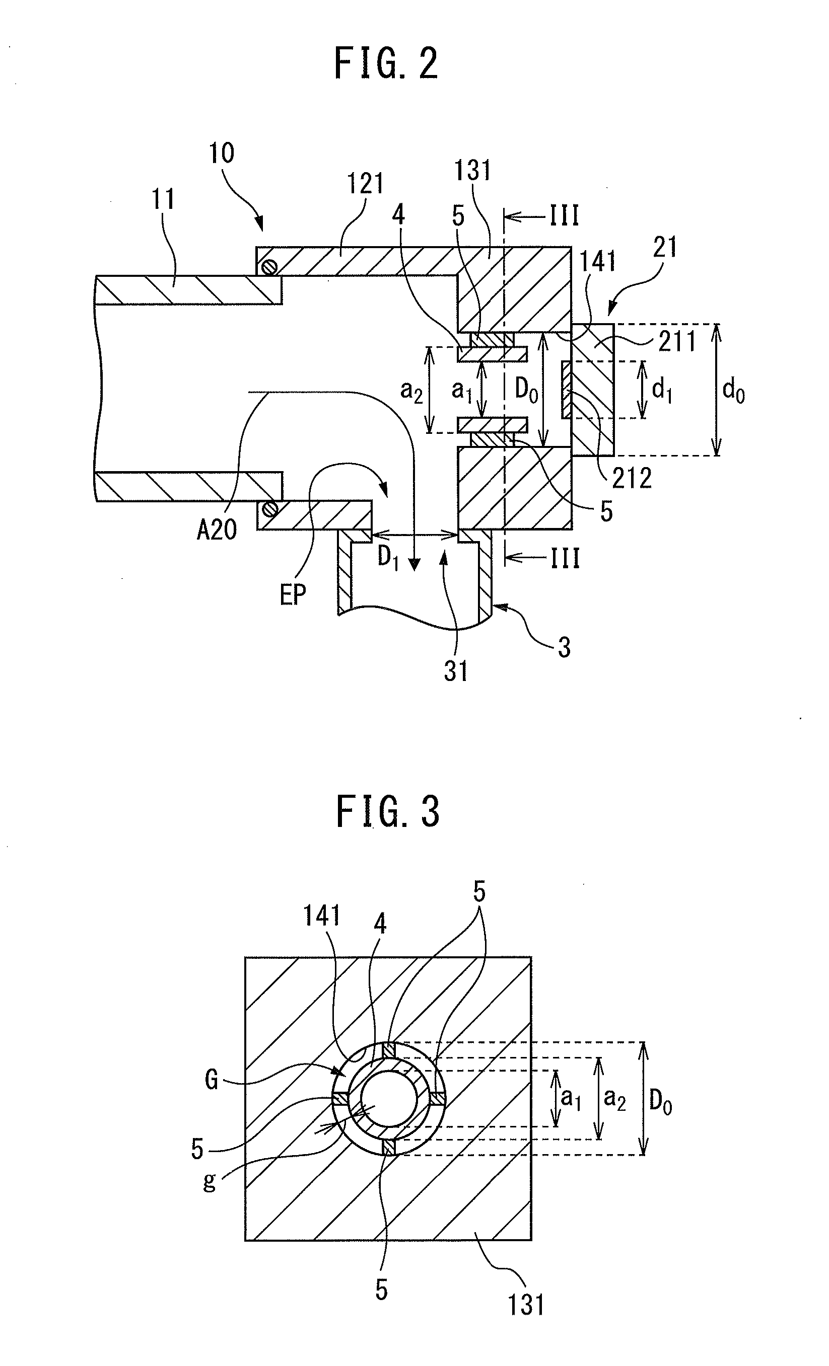
A laser oscillator comprising an electric discharge excitation part having a discharge tube, and generates laser by excitation discharge of a laser gas flow through the inside of the discharge tube, an optical resonance part which has optical components attached to outsides of end walls of the discharge tube, and resonates laser generated in the discharge tube, and blower piping which connects an intake port and exhaust port of the discharge tube to form a circulation path of laser gas. The end walls of the discharge tube are provided with through holes which connect the inside of the discharge tube and the optical components, and blocking members are arranged in the through holes so as to block the flow of laser gas through the through holes toward the optical components.

Description

BACKGROUND OF THE INVENTION[0001]1. Field of the Invention[0002]The present invention relates to a gas circulation type laser oscillator which is mounted in a laser processing machine which is mainly used for cutting, welding, etc. of metal materials and plastic materials etc., and is configured to generate laser by excitation discharge of a laser gas flow through the inside of a discharge tube.[0003]2. Description of the Related Art[0004]Laser oscillators which generate laser by excitation discharge of a mixed gas circulating through a ring-shaped blower path are widely used. Such a laser oscillator is called a “gas circulation type laser oscillator”. In a gas circulation type laser oscillator, dust or particulate matter which enters the blower path during assembly, and a foreign substance such as quartz powder which is produced during excitation discharge due to abrasion of the inner wall of a discharge tube made from quarts may also circulate inside the blower path together with ...

Claims


Application Information

Patent Timeline
IPC IPC(8): H01S3/07H01S3/034H01S3/083H01S3/223H01S3/104H01S3/097H01S3/036
CPCH01S3/073H01S3/09705H01S3/034H01S3/036H01S3/0346H01S3/223H01S3/104H01S3/0835H01S3/2232H01S3/03H01S3/0971
Inventor YOSHIDA, HIROYUKI
Owner FANUC CORP
Learn More