
Fluid separator

Active Publication Date: 2009-04-30
ZEBRA SKIMMERS CORP
View PDF8 Cites 0 Cited by
  • Summary
  • Abstract
  • Description
  • Claims
  • Application Information

AI Technical Summary

Benefits of technology

[0010]Further in the foregoing aspects, a means can be provided for removing from the endless flexible strip quantities of the first fluid that adhere to the endless flexible strip and that means can comprise a scraping annulus through which the successive portions of the endless flexible strip pass. The scraping annulus can have an inside diameter sufficiently sma

Problems solved by technology

These lubricating oils, typically referred to as “tramp oil”, eventually contribute to bacterial growth within the tank holding the aqueous coolant, resulting in a foul odor and reducing the useful life of the aqueous coolant.
Moreover, due to environmental considerations, the oil-contaminated aqueous coolant must be treated as a hazardous waste and its disposal represents an environmental and economic concern.

Method used


Image

  • Fluid separator
  • Fluid separator
  • Fluid separator

Examples


Embodiment Construction

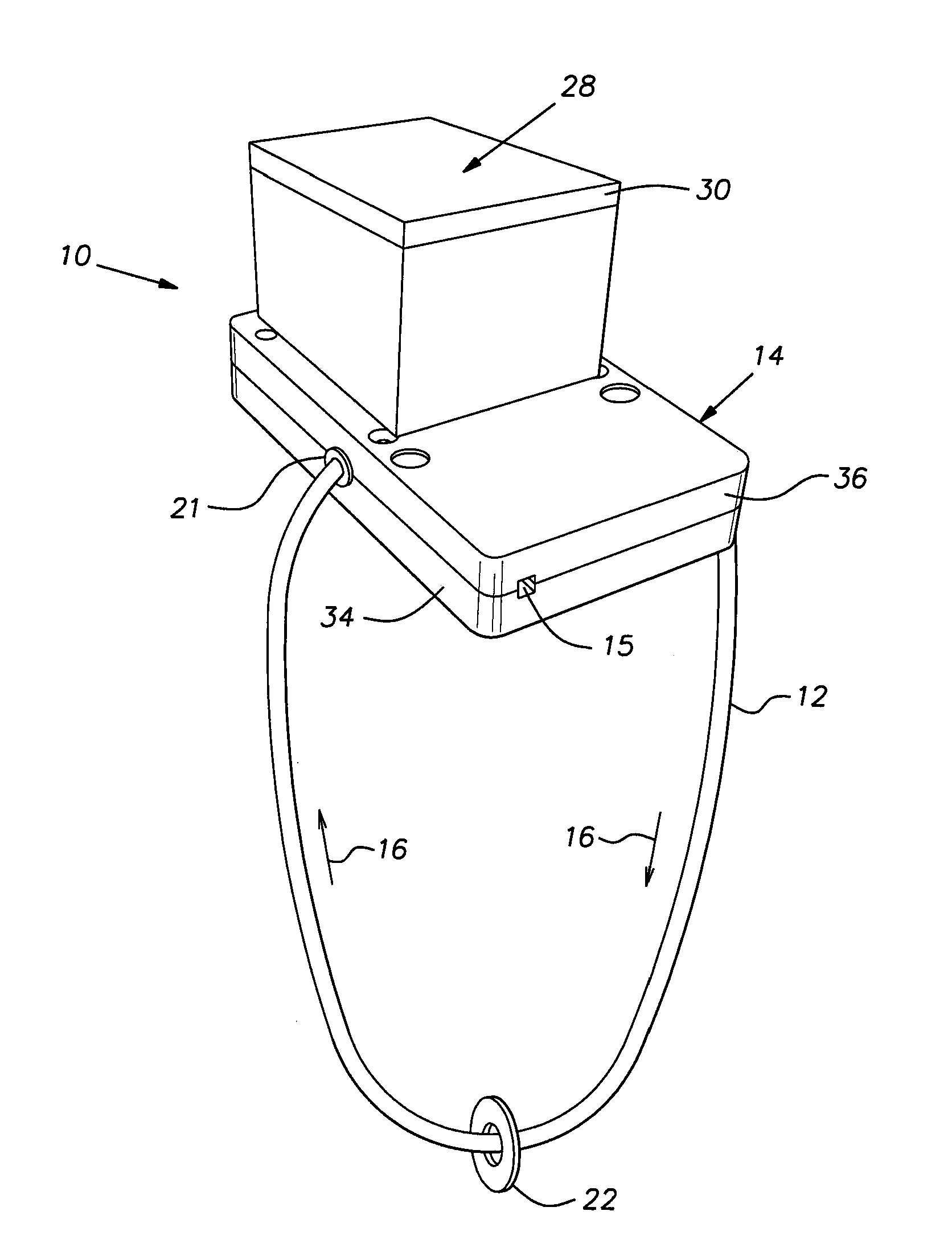
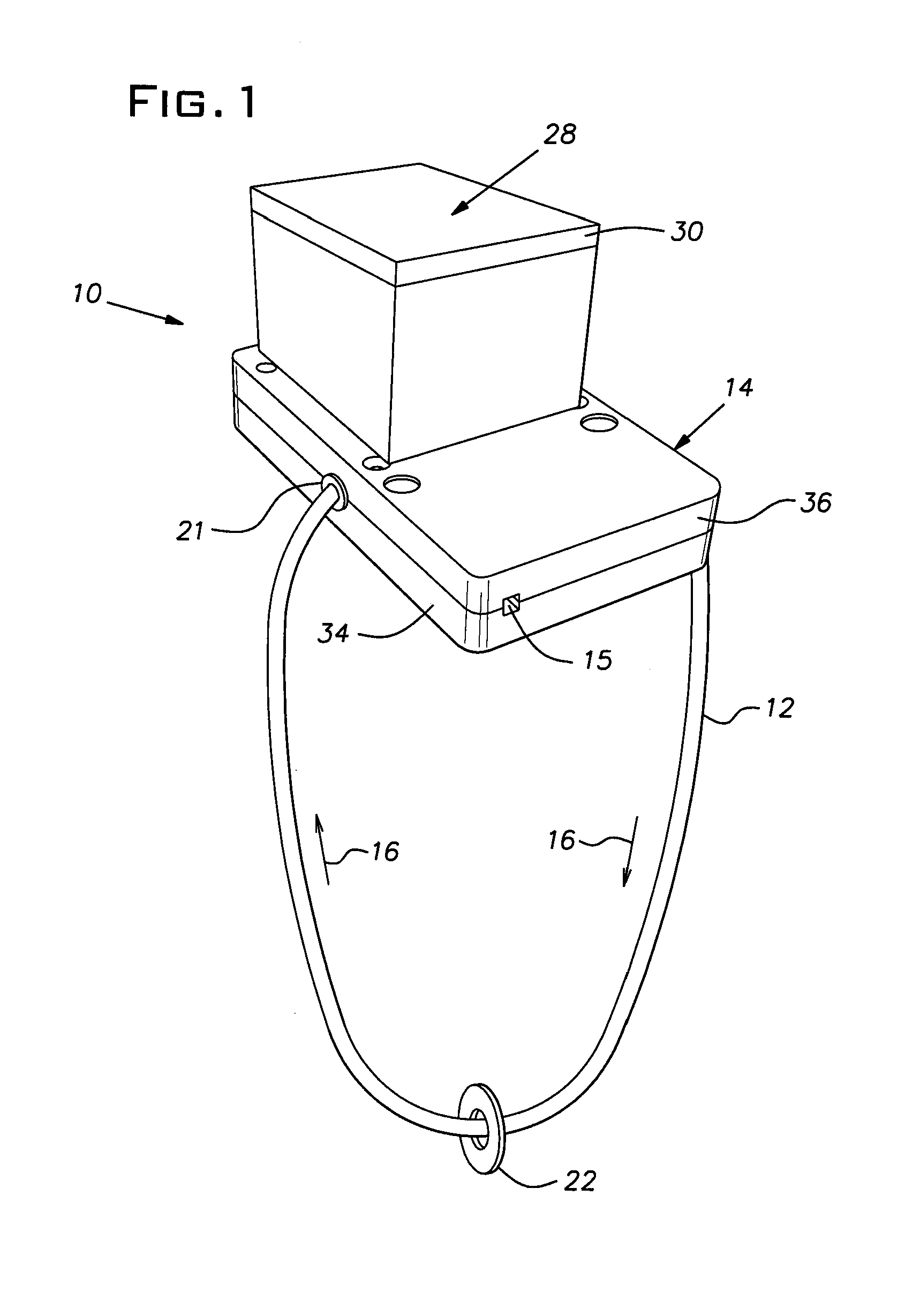
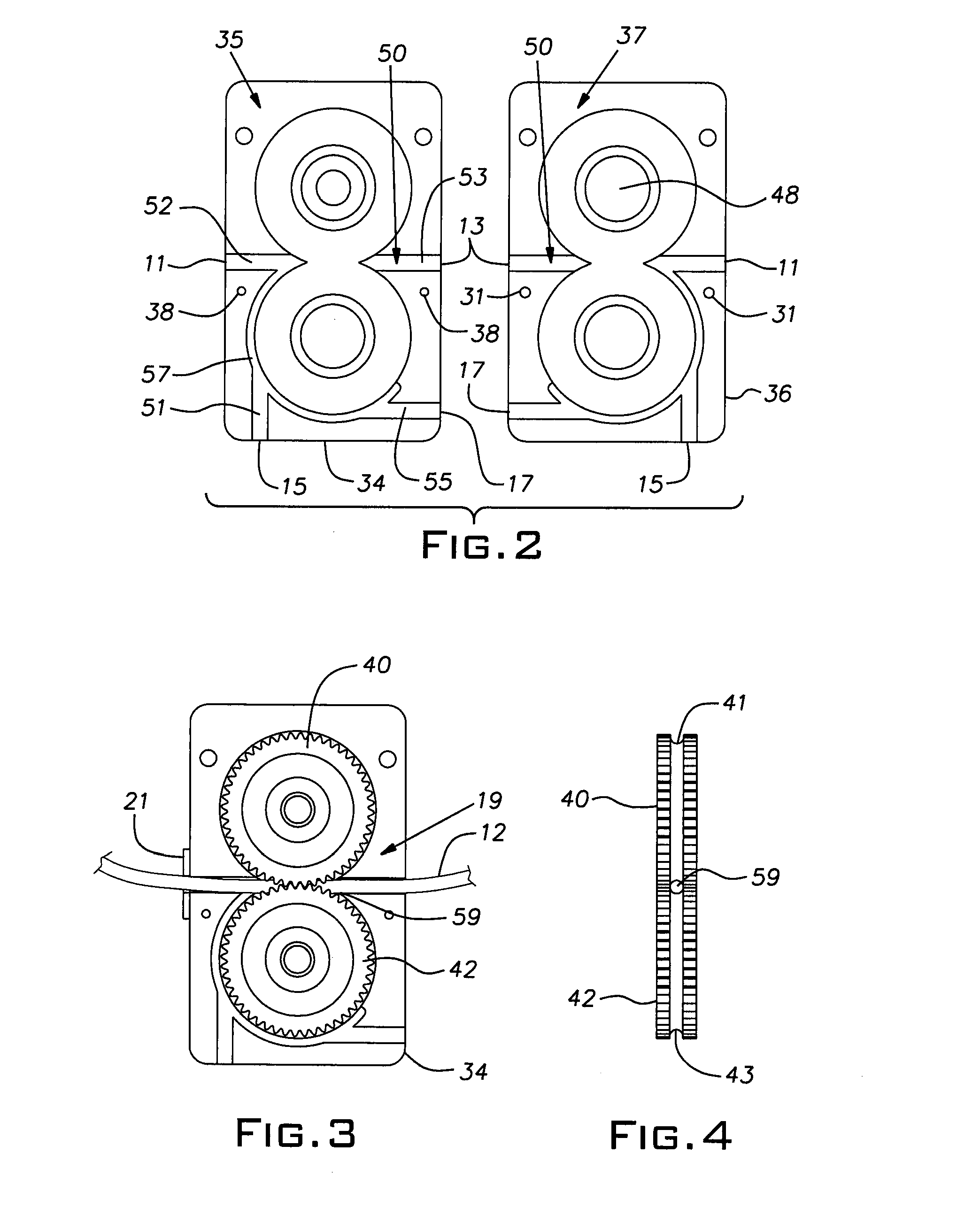
[0017]For the purposes of facilitating an understanding of the principles of the invention, reference will now be made to the embodiment of the invention depicted in the drawings. However, the invention is not limited in its application to the details of construction or the arrangement of components set forth in the drawings or the following description. Other embodiments of the invention are possible, and the invention is capable of being practiced and carried out in ways other than as described. Also, it is to be understood that the terminology and phraseology used in describing the invention is employed for the purpose of promoting an understanding of the invention and should not be considered as limiting. For example, the phrase “process fluid” should be understood to include not only a coolant used in connection with the cutting and cooling functions of a machining process, but also other fluids such as, for example, a wash fluid, or a metal-working fluid that can collect liqui...


PUM

PropertyMeasurementUnit
Angleaaaaaaaaaa
Flexibilityaaaaaaaaaa

Abstract

An apparatus separates a first fluid from a mixture of fluids. The apparatus includes a housing that can have one or more entry openings and one or more exit openings. An endless flexible strip of a material having an affinity for the first fluid is arranged to be advanced through the housing. An advancing assembly advances the endless flexible strip through an entry opening in the housing and through an exit opening in the housing, thereby advancing successive portions of the endless flexible strip sequentially from a position out of contact with the first fluid to a position of contact with the first fluid and again to a position out of contact with the first fluid. More than one pathway can be located within the housing along which the endless flexible strip can be selectively advanced. A means for removing from the endless flexible strip quantities of the first fluid that adhere to the endless flexible strip can be provided.

Description

BACKGROUND OF THE INVENTION[0001]The present invention relates generally to an apparatus for separating fluids and, more specifically, to an apparatus for removing tramp oil from coolants used in machining centers.[0002]There are a variety of instances where it is desired to separate a fluid from a mixture of fluids. For example, in many machining operations, an aqueous coolant is sprayed or flowed at the location or site where a cutting tool engages a workpiece for lubricating and cooling the cutting tool and workpiece. The coolant is then collected in a tank and recycled for continuous use for as long as possible since coolants of this type are fairly expensive and it is advantageous to maintain the coolants in a usable condition. Typical machining operations also employ lubricating oils for lubricating moving parts. Eventually, the lubricating oils drip or flow into the tank where the aqueous coolant is being collected. In the tank, the lubricating oils float upon the surface of ...

Claims


Application Information

Patent Timeline
IPC IPC(8): B01D17/00
CPCY10S210/923B01D17/0202Y02P70/10
Inventor DAVIDIAN, STEVEN
Owner ZEBRA SKIMMERS CORP
Learn More