Image sensor and driving method therefor

Active Publication Date: 2016-06-02
RAYENCE +1
View PDF9 Cites 0 Cited by
  • Summary
  • Abstract
  • Description
  • Claims
  • Application Information

AI Technical Summary

Benefits of technology

[0013]According to the present invention, whether light has been irradiated may be determined by detecting variation between data signals in row lines in a current frame and a previous frame. Therefore, whether light has been irradiated may be promptly and accurately determined using a convenient method. Further, af

Problems solved by technology

Accordingly, there is inconvenience in that manufacturing cost is increased and the design of the image sensor is complicated.
F

Method used


Image

  • Image sensor and driving method therefor
  • Image sensor and driving method therefor
  • Image sensor and driving method therefor

Examples


Example

BEST MODE

[0020]Hereinafter, embodiments of the present invention will be described in detail with reference to the attached drawings.

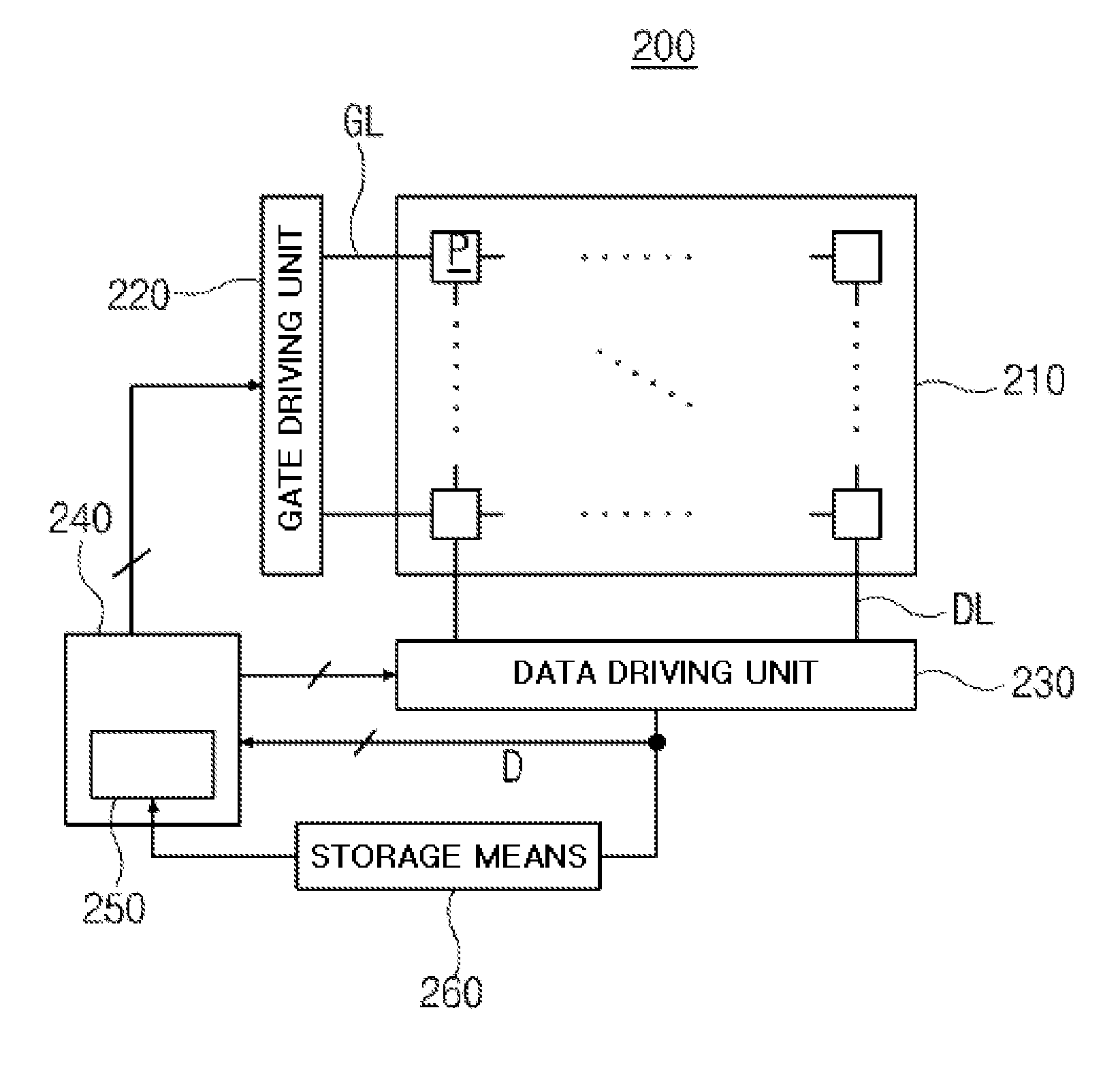
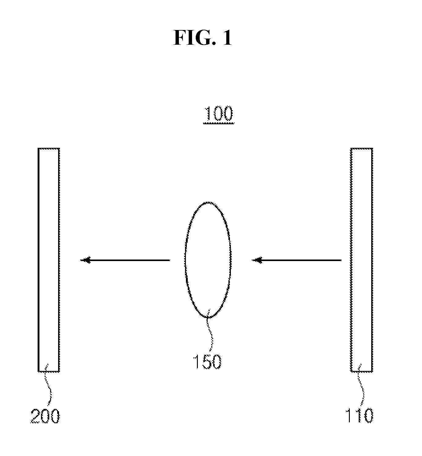
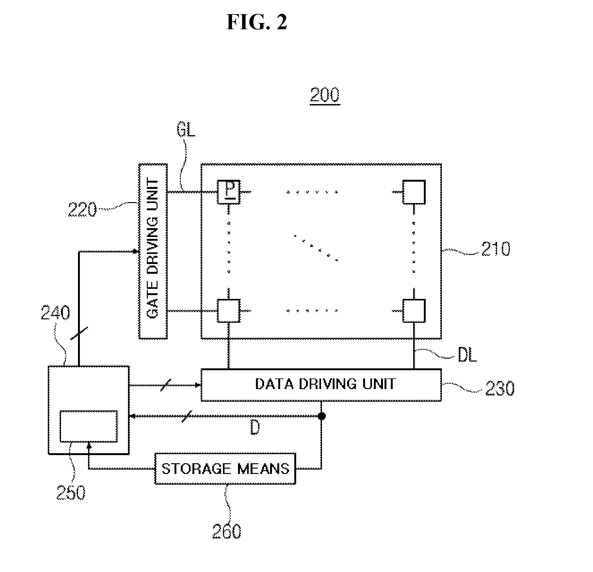
[0021]FIG. 1 is a diagram schematically illustrating an imaging device using an image sensor according to an embodiment of the present invention, and FIG. 2 is a block diagram schematically illustrating an image sensor according to an embodiment of the present invention.

[0022]As an imaging device 100 according to an embodiment of the present invention, an image device for acquiring images by detecting various types of light, such as X-rays or visible rays, may be used. For the convenience of description, an X-ray imaging device for acquiring an X-ray image is given as an example.

[0023]The imaging device 100 may include an X-ray irradiator 110 for generating X-rays and irradiating the X-rays onto a subject 150, and an image sensor 200 for detecting X-rays having passed through the subject.

[0024]Here, the image sensor 200 is a component driven in an auto...


PUM


Abstract

The objective of the present invention is to embody a convenient and reliable image sensor of an auto trigger scheme. The present invention provides a driving method for an image sensor in which pixels are arranged in a matrix form along row lines and column lines and which has a waiting mode and an image obtaining mode, the driving method for an image sensor comprising the steps of: when sequentially selecting a row line, applying a gate signal, and reading out a data signal for each frame in the waiting mode, calculating a variation between the data signal of the currently selected row line and the data signal of the same row line in the previous frame; and if the variation is greater than or equal to a threshold value, determining that light has been radiated.

Description

TECHNICAL FIELD[0001]The present invention generally relates to an image sensor and, more particularly, to an auto trigger-type image sensor, which automatically determines whether light has been irradiated, and to a method for driving the image sensor.BACKGROUND ART[0002]An image sensor, which is a device for detecting external optical image signals and converting the signals into electrical signals, has been mounted and widely used in various types of electronic equipment, and has been chiefly used especially in imaging devices.[0003]In an image sensor, pixels that are photodetection units are arranged in a matrix form along row lines and column lines. In each pixel, a photoelectric conversion element is implemented and configured to convert light irradiated by a light irradiation device into an electrical signal.[0004]Generally, the light irradiation device communicates with an image sensor so as to transmit a synchronizing signal indicating the irradiation of light to the image ...

Claims


Application Information

Patent Timeline
IPC IPC(8): H04N5/378
CPCH04N5/378H04N23/60H04N23/71H04N25/50H04N25/70H04N25/75
Inventor YIM, JO SEONG
Owner RAYENCE
Why Eureka
Try Eureka