
Powder bed additive manufacturing of low expansion glass

a technology of additive manufacturing and powder bed, applied in the field of optics and additive manufacturing, can solve the problems of complex features and difficult manufacturing of many small parts, and achieve the effect of reducing the mass of the mirror substrate, level of stiffness and stability

Inactive Publication Date: 2018-05-10
THE BF GOODRICH CO
View PDF0 Cites 1 Cited by
  • Summary
  • Abstract
  • Description
  • Claims
  • Application Information

AI Technical Summary

Benefits of technology

The patent describes a method for creating a mirror substrate by fusing glass powder material. The process involves creating an optimal three-dimensional mirror topology that minimizes the mass of the substrate while providing stability. The material properties of the substrate can vary in successive layers or based on position within the structure. The technical effect of this method is the creation of a high-quality mirror substrate with a minimized mass and increased stability.

Problems solved by technology

But because glass is fragile, it is challenging to manufacture many small, intricate features with these conventional processes, and such intricate features can be important to manufacturing lightweight optics.

Method used


Image

  • Powder bed additive manufacturing of low expansion glass
  • Powder bed additive manufacturing of low expansion glass
  • Powder bed additive manufacturing of low expansion glass

Examples


Embodiment Construction

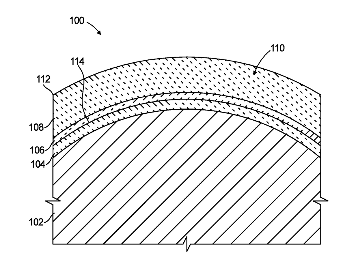
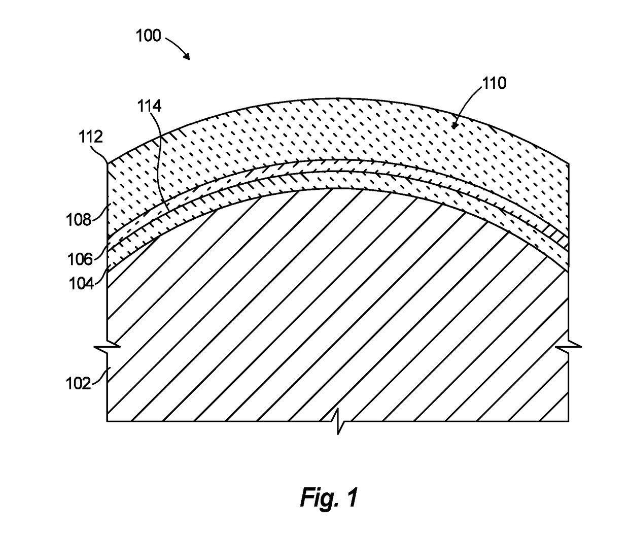
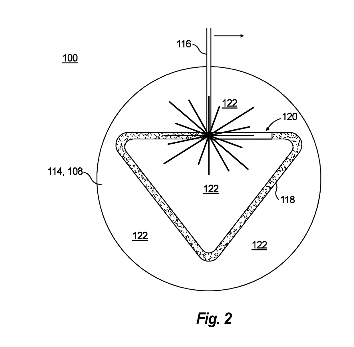
[0016]Reference will now be made to the drawings wherein like reference numerals identify similar structural features or aspects of the subject disclosure. For purposes of explanation and illustration, and not limitation, a partial view of an exemplary embodiment of an optical component in accordance with the disclosure is shown in FIG. 1 and is designated generally by reference character 100. Other embodiments of optical components in accordance with the disclosure, or aspects thereof, are provided in FIG. 2, as will be described. The systems and methods described herein can be used to additively manufacture light-weidth mirror substrates from low thermal expansion glass.

[0017]FIG. 1 shows an optical component 100, e.g., a mirror substrate, on a mandrel 102. A method of forming the optical component 100 includes positioning a preformed glass facesheet 104 on the mandrel 102. The facesheet 104 can be made of titania-silica glass, can be relatively thin, and is contoured for optical ...


PUM

PropertyMeasurementUnit
optical propertiesaaaaaaaaaa
massaaaaaaaaaa
stiffnessaaaaaaaaaa

Abstract

A method of forming an optical component includes fusing glass powder material to a facesheet to form a first core material layer on the facesheet. The method also includes successively fusing glass powder material in a plurality of additional core material layers to build a core material structure on the facesheet. The method can include positioning the facesheet on a mandrel prior to fusing glass powder material to the facesheet. Fusing glass powder material to the facesheet can include fusing the glass powder material to a polishable surface of the facesheet.

Description

BACKGROUND OF THE INVENTION1. Field of the Invention[0001]The present disclosure relates to optics and additive manufacturing, and more particularly to additively manufacturing optics e.g., from low expansion glass.2. Description of Related Art[0002]Conventional lightweight glass mirror substrates are generated with subtractive manufacturing, milling, grinding, polishing, or etching away material from a large glass boule. These processes can create a stiff, lightweight glass structure with a precisely shaped optical surface, which remains stable under thermal and mechanical loads. But because glass is fragile, it is challenging to manufacture many small, intricate features with these conventional processes, and such intricate features can be important to manufacturing lightweight optics.[0003]The conventional techniques have been considered satisfactory for their intended purpose. However, there is an ever present need for improved manufacturing of glass optics such as mirror substr...

Claims


Application Information

Patent Timeline
Patent Type & Authority Applications(United States)
IPC IPC(8): C03B19/01B33Y70/00B33Y10/00B33Y80/00G02B5/10
CPCC03B19/01B33Y70/00G02B5/10B33Y80/00B33Y10/00C03B19/06C03B2201/42
Inventor HARRISON, KRAMEREAST, MATTHEW J.DUNN, DANIEL E.SOUTHARD, BARI M.
Owner THE BF GOODRICH CO
Learn More