Eureka AIR delivers breakthrough ideas for toughest innovation challenges, trusted by R&D personnel around the world.

Apparatus and method for compensating for duty signals

Inactive Publication Date: 2016-06-09
ELECTRONICS & TELECOMM RES INST
View PDF1 Cites 0 Cited by
  • Summary
  • Abstract
  • Description
  • Claims
  • Application Information

AI Technical Summary

Benefits of technology

The present invention provides an apparatus and method for compensating for duty signals that measure and correct the mismatched timing between an I signal and a Q signal having a 25% duty cycle. The apparatus includes a signal input unit, a signal control unit, a combined signal control unit, and a signal output unit. The method involves determining whether the timing of the first signal matches the timing of the second signal, generating a control signal, and outputting the combined signal and logic operation signals. The technical effect of the invention is to improve the accuracy and reliability of timing in electronic devices that use duty signals.

Problems solved by technology

A Gilbert cell mixer used in a common wireless communication transmission stage and a frequency synthesizer requires a high power supply voltage in order to ensure sufficient linearity, and has poor timing characteristics attributable to a mismatch in a voltage current conversion circuit.
However, a passive mixer is problematic in terms of the degree of IF-RF separation, and requires the generation of a 25% duty signal within a local signal due to a crosstalk problem.
The 25% duty signal has a very strong possibility that a timing mismatch may occur between an I signal and a Q signal.

Method used


Image

  • Apparatus and method for compensating for duty signals
  • Apparatus and method for compensating for duty signals
  • Apparatus and method for compensating for duty signals

Examples


Embodiment Construction

[0035]The present invention may be subjected to various modifications and have various embodiments. Specific embodiments are illustrated in the drawings and described in detail below. However, this is not intended to limit the present invention to these specific embodiments, but is intended to encompass all modifications, equivalents and substitutions that fall within the technical spirit and scope of the present invention.

[0036]The terms used herein are used merely to describe embodiments, and are not intended to limit the inventive concept. A singular form may include a plural form, unless otherwise defined.

[0037]Embodiments of the present invention will be described in detail below with reference to the accompanying drawings.

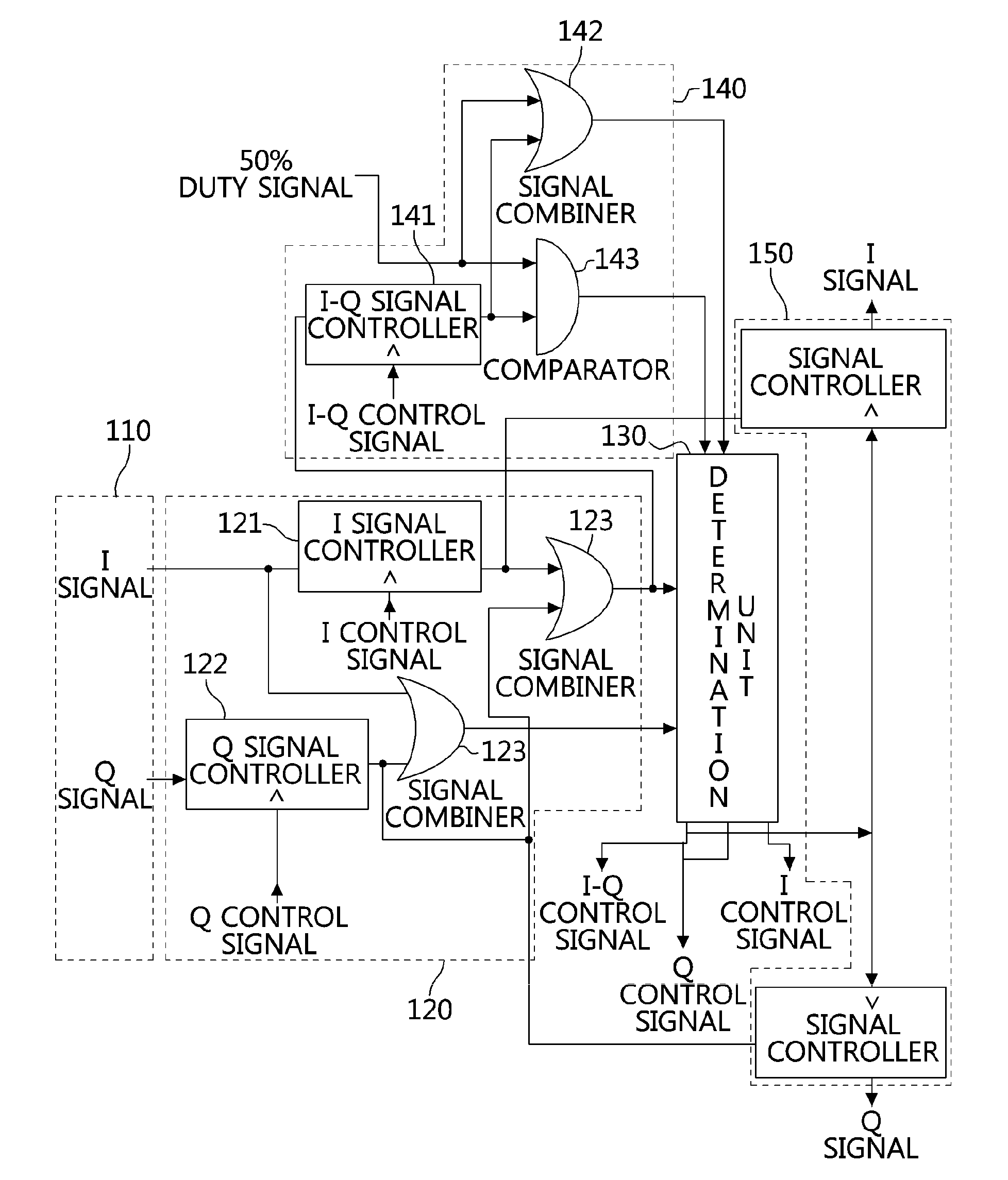
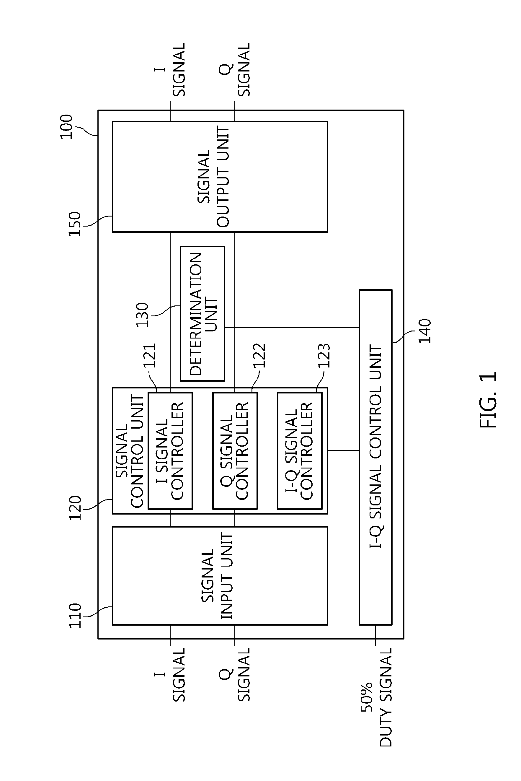
[0038]FIG. 1 is a diagram illustrating the functional configuration of an apparatus for compensating for the duty signals of an I signal and a Q signal according to an embodiment of the present invention.

[0039]The apparatus 100 for compensating for the duty s...


PUM


Abstract

An apparatus and method for compensating for duty signals are disclosed herein. The apparatus for compensating for duty signals includes a signal input unit, a signal control unit, a combined signal control unit, a determination unit, and a signal output unit. The signal input unit receives a first signal and a second signal. The signal control unit controls the timing of the first and second signals based on first and second control signals, and outputs a combined signal. The combined signal control unit outputs first and second logic operation signals. The determination unit generates the first and second control signals if the timing of the first signal does not match the timing of the second signal, outputs the generated first and second control signals, and applies a third control signal to the combined signal control unit. The signal output unit outputs the first and second signals.

Description

CROSS-REFERENCE TO RELATED APPLICATION[0001]This application claims the benefit of Korean Patent Application No. 10-2014-0174751, filed Dec. 8, 2014, which is hereby incorporated by reference herein in its entirety.BACKGROUND[0002]1. Technical Field[0003]Embodiments of the present invention relate generally to an apparatus and method for compensating for duty signals and, more particularly, to a method of increasing the timing accuracy of a 25% duty signal required in the transmission stage or frequency synthesizer of a wireless communication system and to an apparatus and method for compensating for the timing error between an I signal and a Q signal.[0004]2. Description of the Related Art[0005]A Gilbert cell mixer used in a common wireless communication transmission stage and a frequency synthesizer requires a high power supply voltage in order to ensure sufficient linearity, and has poor timing characteristics attributable to a mismatch in a voltage current conversion circuit. Ac...

Claims


Application Information

Patent Timeline
IPC IPC(8): H03K5/156
CPCH03K5/1565
Inventor LEE, SEUNG-SIKKIM, JAE-YOUNGNAM, HONG-SOONCHOI, SANG-SUNG
Owner ELECTRONICS & TELECOMM RES INST
Why Eureka
Eureka Blog
Learn More