Pneumatic tire

Active Publication Date: 2016-06-23
SUMITOMO RUBBER IND LTD
View PDF3 Cites 17 Cited by
  • Summary
  • Abstract
  • Description
  • Claims
  • Application Information

AI Technical Summary

Benefits of technology

[0005]It is therefore, an object of the present invention to provide a pneumatic tire, in which

Problems solved by technology

In such block pattern tires, however, due to the pitch sound and pumping sound, noise performance when running on pavements such as well paved asphalt roads is not good.
Even if th

Method used


Image

  • Pneumatic tire
  • Pneumatic tire
  • Pneumatic tire

Examples


Example

[0036]Embodiments of the present invention will now be described in detail in conjunction with the accompanying drawings.

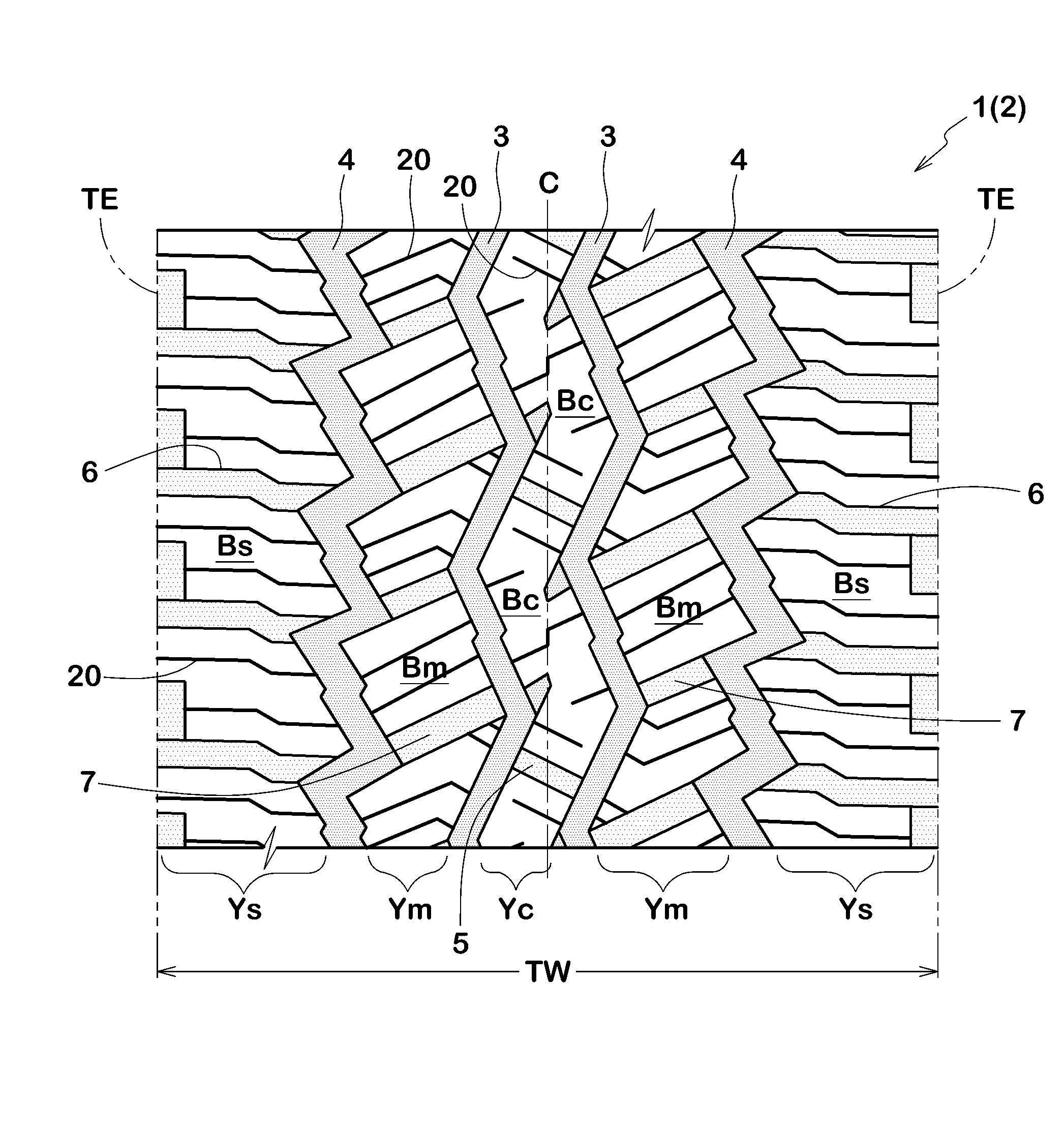
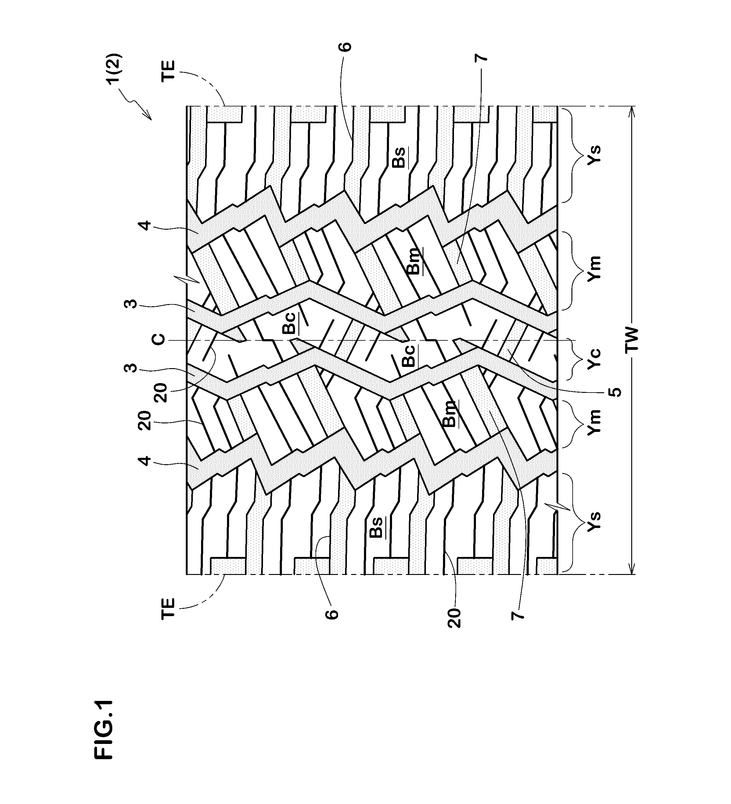
[0037]As shown in FIG. 1, a pneumatic tire 1 as an embodiment of present invention comprises a tread portion 2 provided with a pair of crown circumferential grooves 3 disposed one on each side of the tire equator C,

a pair of shoulder circumferential grooves 4 disposed axially outside the crown circumferential grooves 3,

a plurality of crown lateral grooves 5 extending across the entire axial width of a crown region Yc defined between the crown circumferential grooves 3, and

a plurality of shoulder lateral grooves 6 extending across the entire axial width of a shoulder region Ys defined between each of the shoulder circumferential grooves 4 and the adjacent tread edge Te.

[0038]Thereby, the crown region Yc is divided into a plurality of center blocks BC, and

each of the shoulder regions Ys is divided into a plurality of shoulder blocks Bs.

[0039]In this example, the tre...


PUM


Abstract

A pneumatic tire is provided in the tread portion with zigzag crown circumferential grooves 3 having pitch length Pc, zigzag shoulder circumferential grooves 4 having pitch length Ps, crown lateral grooves 5 inclined at an angle θc, and shoulder lateral grooves 6 inclined at an angle θs wherein Ps>Pc and θs<θc. Both ends of the respective crown lateral grooves 5 are connected to the zigzag groove segments 3a or 3b of the crown circumferential grooves 3 which groove segments 3a or 3b are inclined with respect to the tire axial direction to the opposite direction to the inclining direction of the crown lateral grooves 5. The number NS of the shoulder lateral grooves 6 is more than the number Nc of the crown lateral grooves 5.

Description

BACKGROUND OF THE INVENTION[0001]The present invention relates to a pneumatic tire, more particularly to a tread pattern capable of improving noise performance.[0002]In general, tires for winter use such as snow tire designed for running on snowy roads are provided in the tread portion with a block pattern in order to improve on-snow performance. In such block pattern tires, however, due to the pitch sound and pumping sound, noise performance when running on pavements such as well paved asphalt roads is not good.[0003]On the other hand, the Japanese Patent Application Publication No. 2012-011981 (corresponding to US-2012-000586A1) discloses a pneumatic tire which is as shown in FIG. 4 provided with a crown circumferential groove (a) disposed on each side of the tire equator C, a shoulder circumferential groove (b) disposed on the axially outside of each of the crown circumferential grooves (a), crown lateral grooves (d) extending between the crown circumferential grooves (a), middle...

Claims


Application Information

Patent Timeline
IPC IPC(8): B60C11/03
CPCB60C11/0327B60C2011/0372B60C2011/0346B60C11/0318B60C11/0306B60C11/11B60C2011/0358
Inventor TAKAYAMA, HITOSHI
Owner SUMITOMO RUBBER IND LTD
Why Eureka
Try Eureka