Raman amplifier and method for pumping a Raman amplifier

Inactive Publication Date: 2006-05-09
ALCATEL SOCIETE ANONYME
View PDF9 Cites 1 Cited by
  • Summary
  • Abstract
  • Description
  • Claims
  • Application Information

AI Technical Summary

Benefits of technology

[0016]It is in view of the above prior art an objective of the present invention to provide for a broadened gain curve of a Raman am

Problems solved by technology

Light propagating in such systems is prone to attenuation.
The reflected waves interfere constructively and result in a respective intensity peak at the pa

Method used


Image

  • Raman amplifier and method for pumping a Raman amplifier
  • Raman amplifier and method for pumping a Raman amplifier
  • Raman amplifier and method for pumping a Raman amplifier

Examples


Example

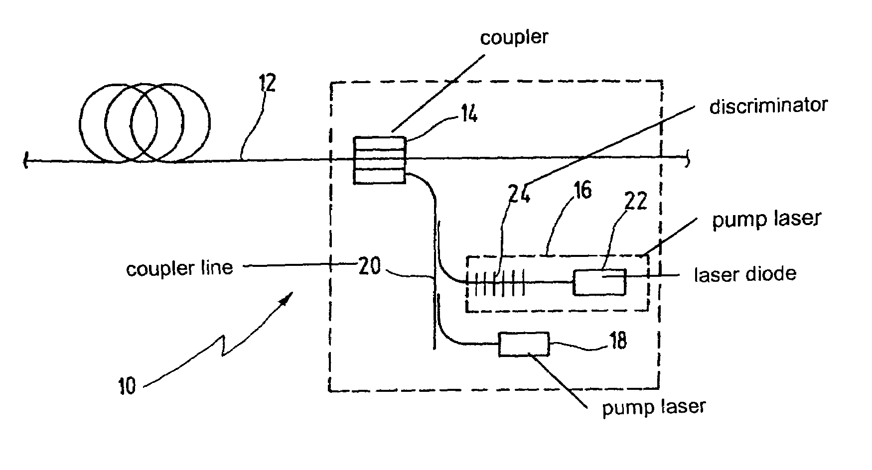
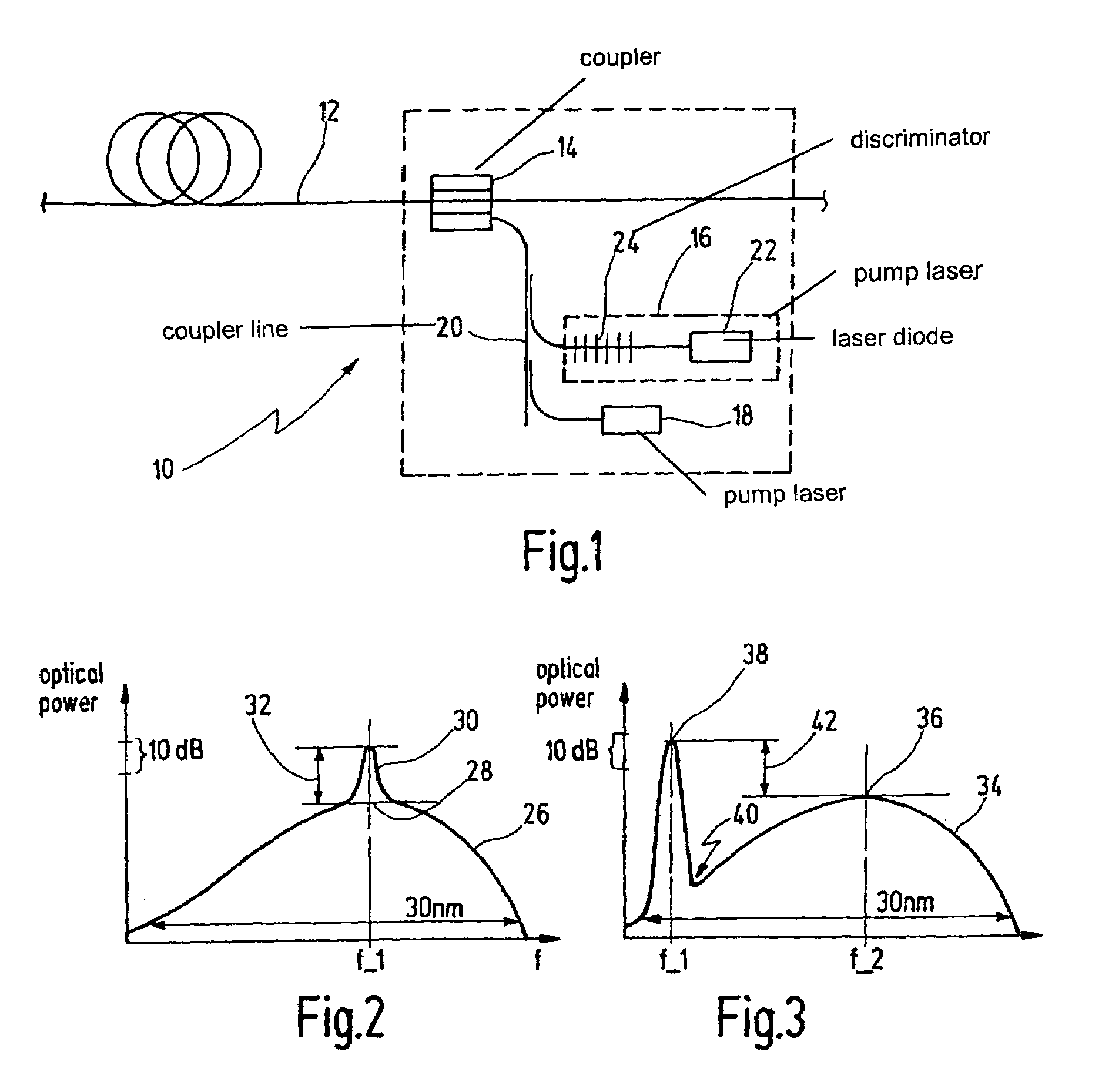
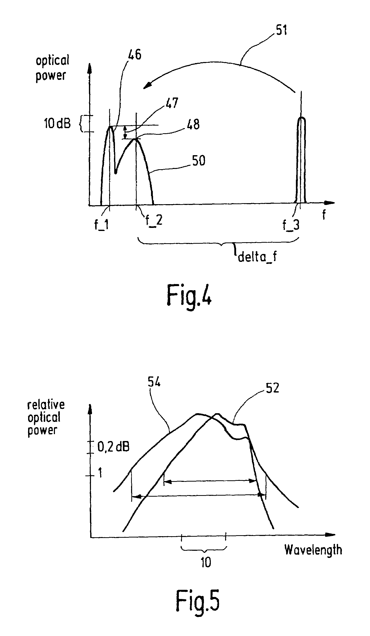
[0046]In FIG. 1, a pump module 10 is coupled to a Raman amplifying fiber 12 by a coupler 14, e.g. wavelength-division-multiplexer 14. An input signal enters the depicted fiber 12 on the left. The amplified signal leaves the fiber 12 at the right. Pump module 10 comprises a first pump laser module 16 and a second pump laser module 18. Both pump laser modules 16, 18 may inject into a coupler line segment 20 that is coupled to coupler 14. The first pump laser module 16 comprises at least a laser diode 22 and a frequency discriminator 24, preferably a Fiber Bragg Grating. Instead of a single laser diode 22, an array of laser diodes 22 may be utilised. Pump laser module 18 may comprise a high-power Raman laser.

[0047]A semi-conductor laser diode 22 shows, in general, a broad emission curve of optical power output versus frequency. The value of 4 THz (30 nm) represents a typical curve broadness of a semi-conductor laser diode 22. For utilization of laser diodes 22 a pump source, lasing at ...


PUM


Abstract

A Raman amplifier (10) including at least one amplifying fiber (12) and a coupler (14) for coupling at least first (16) and second (18) pump laser modules to the amplifying fiber (12), the first pump laser module (16) including a frequency discriminator (24) for selecting an optical frequency to be emitted with an optical power exceeding an optical power of remaining optical frequencies that are also emitted by the first pump laser module (16). The first optical frequency is spaced apart from a local maximum (28; 36; 48) in optical power of the remaining optical frequencies, and the second pump laser module (18) emits at an optical frequency one Stokes-frequency above the frequency of the local maximum (28; 36; 48). The first optical frequency and the frequency of the local maximum are chosen on Stokes-frequency above the signal frequency range. As a consequence, the Raman gain provided in the Raman amplifying fiber 12 is broadened.

Description

BACKGROUND OF THE INVENTION[0001]The invention is based on a priority application EP 03 360 006.5 which is hereby incorporated by reference.[0002]The present invention relates to a Raman amplifier comprising at least one length of Raman amplifying fiber and at least a coupler for coupling at least a first pump laser module and a second pump laser module to said Raman amplifying fiber, the first pump laser module comprising a frequency discriminator for selecting an optical frequency to be emitted with an optical power exceeding an optical power of remaining optical frequencies that are also emitted by said first pump laser module.[0003]Further, the present invention relates to a method of pumping a Raman amplifier comprising the steps of providing at least one length of Raman amplifying fiber, coupling at least a first pump laser module and a second pump laser module to said Raman amplifying fiber and, selecting an optical frequency to be emitted by the first pump laser module with ...

Claims


Application Information

Patent Timeline
IPC IPC(8): H01S3/00H01S3/094H01S3/0941H01S3/30H01S5/14H04B10/291
CPCH04B10/2916H01S3/302H01S3/094003H01S3/09415H01S5/141H01S5/146
Inventor MONGARDIEN, DOMINIQUEMARTINELLI, CATHERINEBAYART, DOMINIQUE
Owner ALCATEL SOCIETE ANONYME
Why Eureka
Try Eureka