
Vehicle-reversing display system capable of automatically switching multiple field-of-view modes and vehicle-reversing image capture device

a display system and vehicle technology, applied in closed circuit television systems, color television details, television systems, etc., can solve the problems of blind zone, inability to realize the real situation behind the vehicle by the ultrasonic sensor, and inability to effectively detect obstacles by conventional ultrasonic sensors

Inactive Publication Date: 2016-06-23
SEEWAYS TECH
View PDF1 Cites 7 Cited by
  • Summary
  • Abstract
  • Description
  • Claims
  • Application Information

AI Technical Summary

Benefits of technology

The present invention provides a system and device for capturing images of a vehicle reversing. The device automatically switches between different modes based on the distance of obstacles in front and behind the vehicle. This results in a display that shows the real situation behind the vehicle while reversing. The technical effect of this patent is to improve safety and awareness for drivers while reversing their vehicles.

Problems solved by technology

Moreover, if the detecting height is lower than 30-45 centimeters, the conventional ultrasonic sensor is unable to effectively detect the obstacle.
However, since the driver cannot realize the distance or the position of the obstacle through the ultrasonic sensor, the driver cannot realize the real situation behind the vehicle by the ultrasonic sensor.
However, since the horizontal viewing angle of the conventional vehicle-reversing camera is at most 140 to 150 degrees, the narrow viewing angle may result in a blind zone.
Moreover, the field of view of the conventional vehicle-reversing camera cannot be automatically adjusted.
Consequently, if the vehicle is close to an object with a vertical plane, the possibility of causing collision or accident increases because the conventional vehicle-reversing camera cannot capture the image of the scene from the top field of view.
For example, if a ravine, a cliff, a harbor embankment or any other object with the vertical plane is behind a vehicle, the driver cannot judge the real situation behind the vehicle because the image cannot be captured from the top field of view.
Consequently, the rear wheels possibly fell into the ravine or the cliff, or collide with the harbor embankment.
However, it is not convenient for the user to switch the operating mode because the action of reversing the vehicle has to be continuously done.

Method used


Image

  • Vehicle-reversing display system capable of automatically switching multiple field-of-view modes and vehicle-reversing image capture device
  • Vehicle-reversing display system capable of automatically switching multiple field-of-view modes and vehicle-reversing image capture device
  • Vehicle-reversing display system capable of automatically switching multiple field-of-view modes and vehicle-reversing image capture device

Examples


Embodiment Construction

[0017]The present invention will now be described more specifically with reference to the following embodiments. It is to be noted that the following descriptions of preferred embodiments of this invention are presented herein for purpose of illustration and description only. It is not intended to be exhaustive or to be limited to the precise form disclosed.

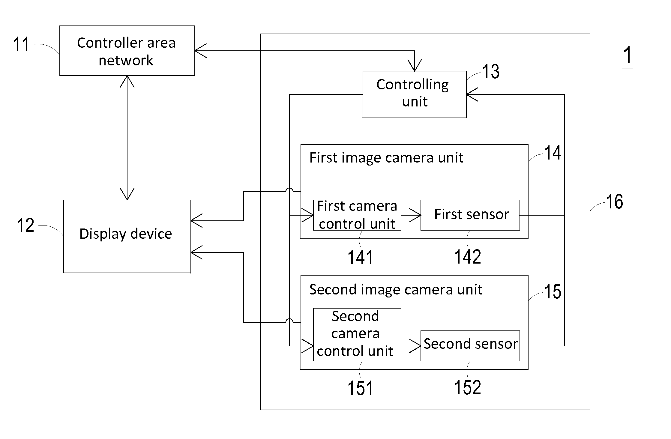
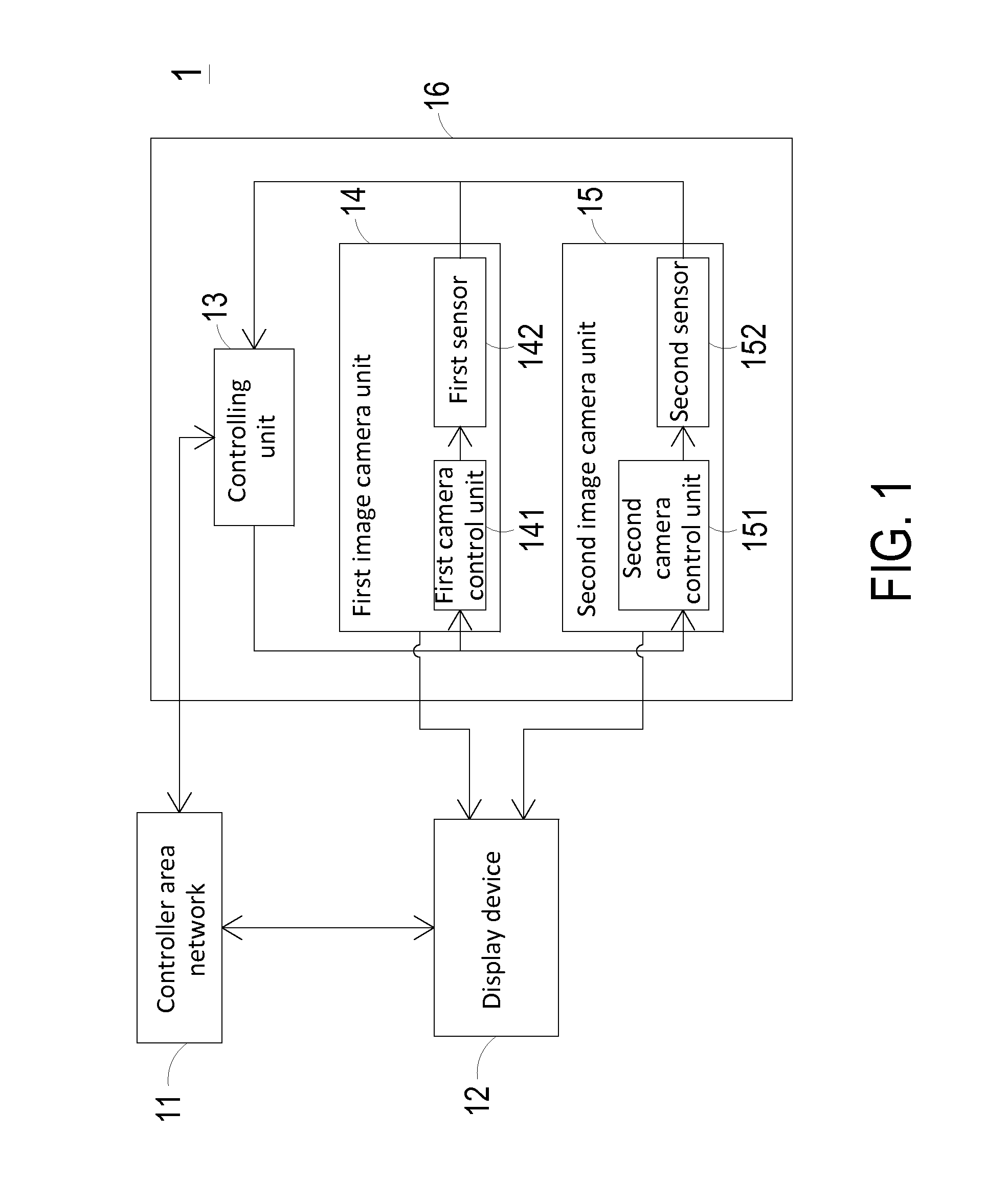
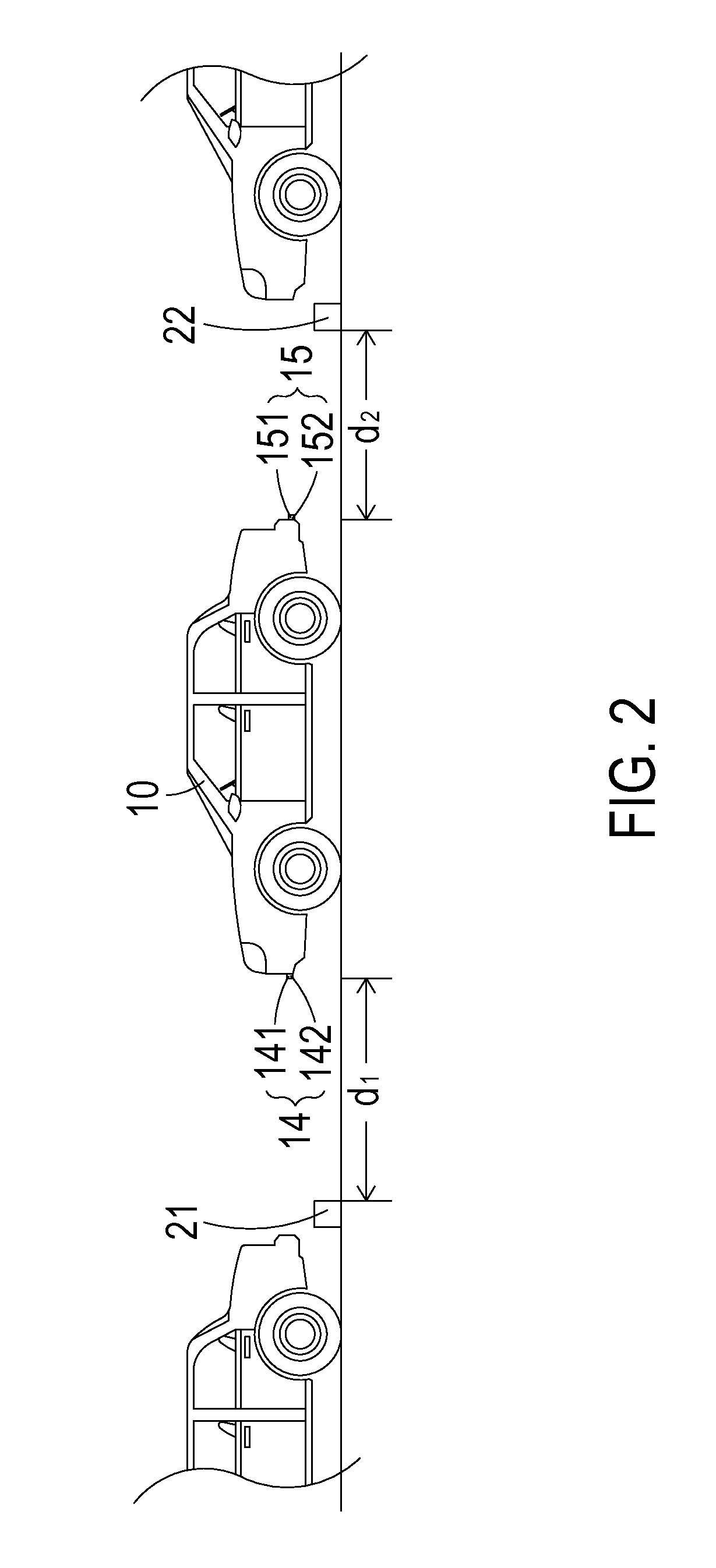
[0018]FIG. 1 is a schematic functional block diagram illustrating a vehicle-reversing display system according to an embodiment of the present invention. The vehicle-reversing display system 1 is applied to a vehicle 10 (see FIG. 2). The vehicle-reversing display system 1 comprises a controller area network (also referred as a CAN Bus) 11, a display device 12, and a vehicle-reversing image capture device 16. The controller area network 11 is connected with a vehicular computer (not shown). The vehicular computer is installed in the vehicle 10 for providing plural vehicle operating parameters. The plural vehicle operating paramete...


PUM


Abstract

A vehicle-reversing display system includes a controller area network, a vehicle-reversing image capture device and a display device. The vehicle-reversing image capture device includes a controlling unit, a first image camera unit and a second image camera unit. The first image camera unit includes a first camera control unit and a first sensor. The second image camera unit includes a second camera control unit and a second sensor. The controlling unit judges a driving scenario according to vehicle-reversing parameters from the controller area network. The first image camera unit and the second image camera unit are automatically enabled or disabled according to the driving scenario. The first image camera unit and the second image camera unit are automatically operated in a wide field-of-view mode, a normal field-of-view mode, or a top field-of-view mode under control of the first camera control unit and the second camera control unit according to a first distance from a first obstacle and a second distance from a second obstacle.

Description

FIELD OF THE INVENTION[0001]The present invention relates to a vehicle-reversing display system, and more particularly to a vehicle-reversing display system capable of automatically switching multiple field-of-view modes by image object detection and a vehicle-reversing image capture device thereof.BACKGROUND OF THE INVENTION[0002]With the improving development of the transmission system and the materials science and the economic growth, vehicles have high flexibility and popularity. Consequently, the users spend less time going to their destinations. As the number of the vehicle users gradually increases, vehicle safety is getting more and more important.[0003]Conventionally, the vehicle safety techniques are aimed at the improvements about the field of view (FOV) of the travelling vehicle and the safety distance between a specified vehicle and the vehicles at the front side, rear side, left side, or right side of the specified vehicle. Moreover, the researches about the auxiliary ...

Claims


Application Information

Patent Timeline
Patent Type & Authority Applications(United States)
IPC IPC(8): B60R1/00B60R11/04H04N7/18
CPCB60R1/00H04N7/181B60R2300/802B60R2300/404B60R11/04H04N7/18B60R2300/70B60R2300/806B60R1/28
Inventor YANG, TUNG-SHINCHO, HSUN-TAOHUANG, HO-KANGHSU, CHEN-KUOLIN, MINGHUA
Owner SEEWAYS TECH
Learn More