Morphing Foil or Wing

a technology of morphing foil and wing, applied in the field of morphing foil or wing and vehicle, can solve the problems of high cost, complex structure of wing, and introduction of complex control issues

Active Publication Date: 2016-06-23
BLUE BEAR SYST RES
View PDF5 Cites 23 Cited by
  • Summary
  • Abstract
  • Description
  • Claims
  • Application Information

AI Technical Summary

Problems solved by technology

However, such wings are very complex, introduce complex control issues and are highly expensive and therefore inappropriate for unmanned air vehicles (UAVs).

Method used


Image

  • Morphing Foil or Wing
  • Morphing Foil or Wing
  • Morphing Foil or Wing

Examples


Embodiment Construction

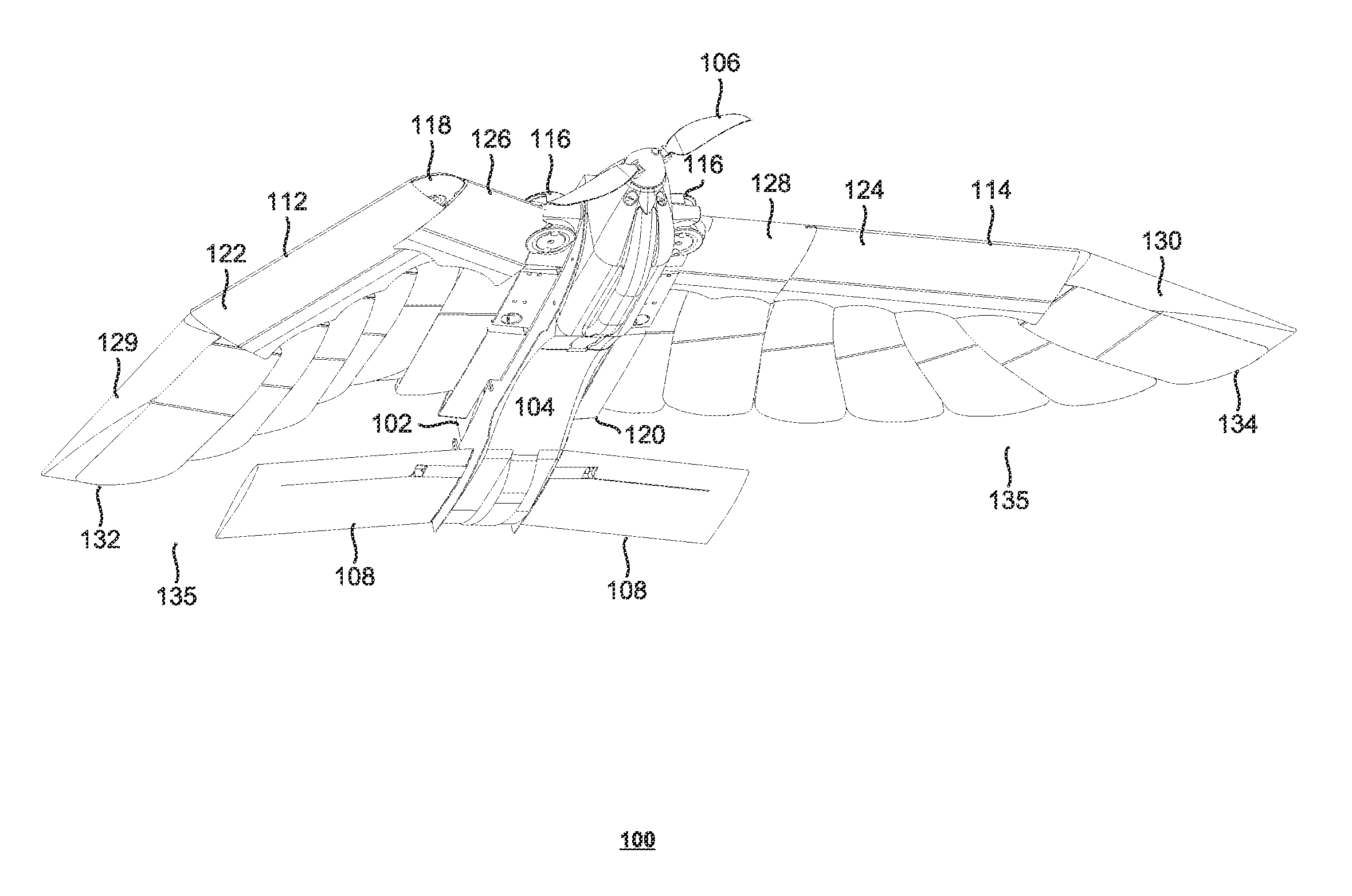
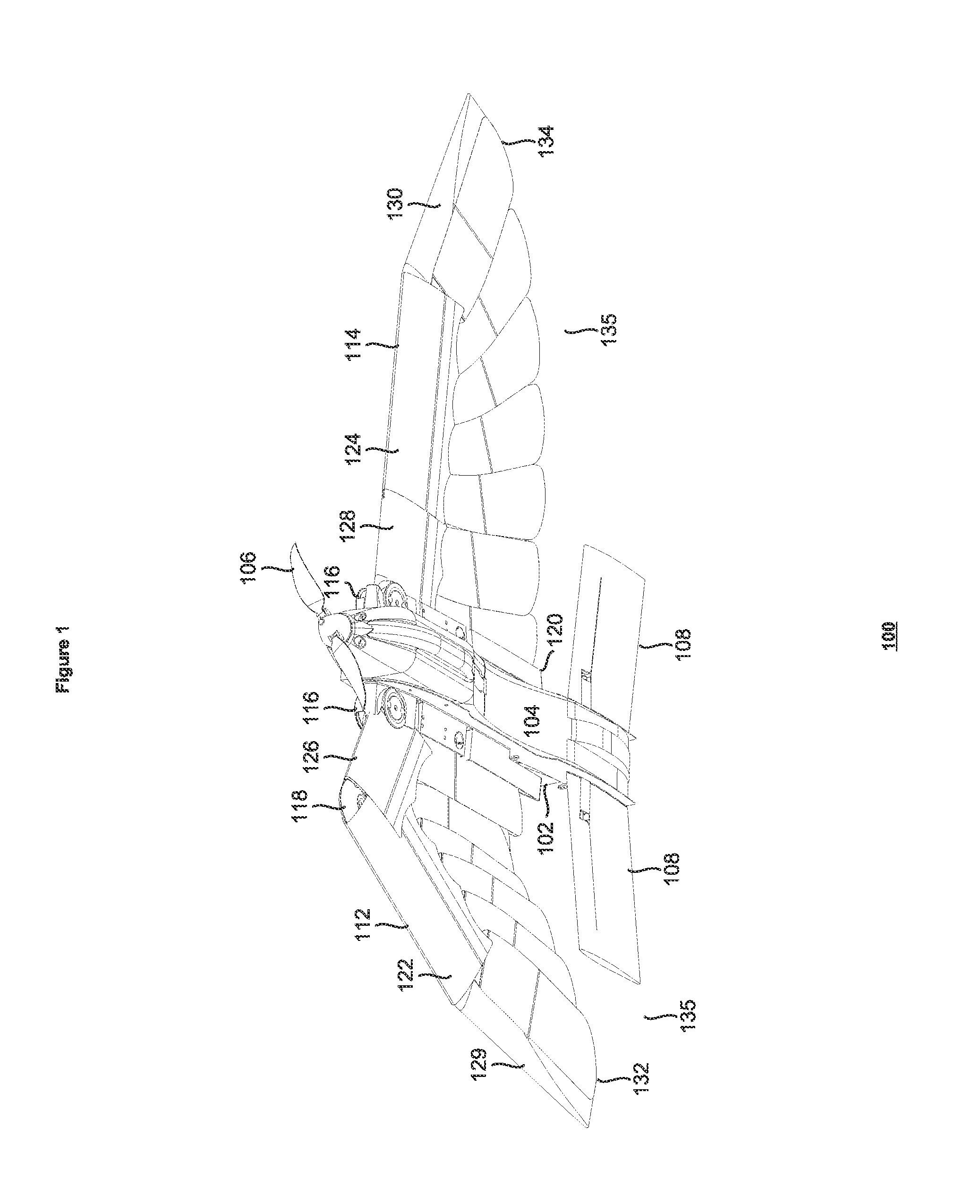
[0016]Referring to FIG. 1, there is shown a perspective view 100 of a UAV 102. The UAV 102 comprises a fuselage 104 bearing a propeller 106, tailerons 108 and a tail 110, as well as a pair of wings 112 and 114, coupled to the fuselage 104 via a housing 120.

[0017]The leading edge of the wings 112 and 114 is jointed. Each wing 112 and 114 comprises a main pivot 116 and a wrist joint 118. In the illustrated figure, only the right wrist joint is visible due to the wing 112 being in a tucked position or state, while the other wing 114 is in an extended position or state.

[0018]Each wing comprises a wing hand section 122 and 124, a wing arm section 126 and 128, and a tip fairing 129 and 130. Each wing also has a plurality of feathers 135, such as, for example the distal most feather 132 and 134 relative to the fuselage. In the present embodiment, each wing 112 and 114 has seven lower feathers, which are visible in FIG. 1 and seven upper feathers. The feathers 135 are arranged to overlap in...


PUM


Abstract

Embodiments of the present invention relate to an adaptable wing having a variable geometry for influencing aerodynamic performance, the wing comprising a jointed leading edge having a main pivot, and a wrist joint, with a wing arm therebetween, 5 and a distal wing hand depending from the wrist joint; the wing being reciprocally actuable, via the main pivot and wrist joint, between a first state having an extended wing planform and a second state having a tucked wing planform.

Description

FIELD OF THE INVENTION[0001]Embodiments of the present invention relate to a morphing foil or wing and vehicle comprising such a foil or wing.BACKGROUND TO THE INVENTION[0002]It is well known to change the planform, via wing configuration changes, to achieve varying performance objectives for aircraft. For example, modern combat planes have variable sweep wing geometries that are deployed according to immediate performance requirements such as subsonic cruising, take-off and landing, which will have a corresponding, high-aspect ratio wing geometry, as compared to supersonic flight, which will have a different corresponding geometry, such as fully-swept back wings to mitigate drag. Such combat planes include, for example, the Panavia Tornado, F-14 Tomcat and MiG-27. Being able to make significant geometric changes to an aircraft's wing during flight increases the flexibility and overall suitability of the aircraft for disparate missions or disparate parts of a mission. However, such ...

Claims


Application Information

Patent Timeline
Patent Type & Authority Applications(United States)
IPC IPC(8): B64C3/54B64C39/02B64C3/40
CPCB64C3/546B64C3/40B64C2201/102B64C39/024B64C2003/543B64C3/54Y02T50/10B64C3/38B64C33/02B64U30/12
Inventor SNOOK, MICHAEL
Owner BLUE BEAR SYST RES
Why Eureka
Try Eureka