Tree Box Filter with Hydromodification Panels

a filter and tree box technology, applied in the field of assemblies and methods, can solve the problems of limited capacity of vault-shaped containers to hold bioretention media, gravel, other container materials, additional space, coordination, time, fuel, labor,

Inactive Publication Date: 2016-06-23
OLDCASTLE PRECAST
View PDF4 Cites 15 Cited by
  • Summary
  • Abstract
  • Description
  • Claims
  • Application Information

AI Technical Summary

Benefits of technology

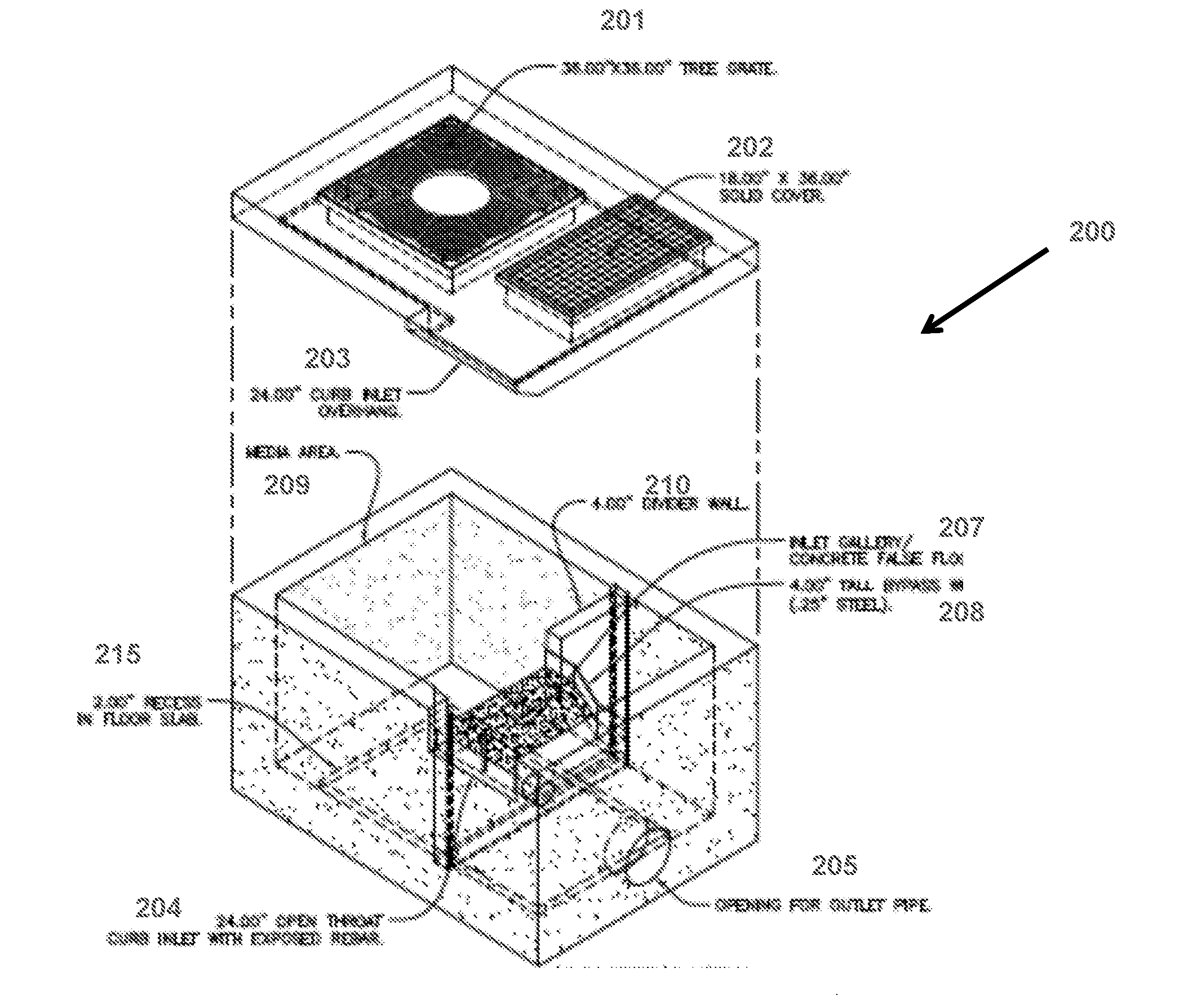
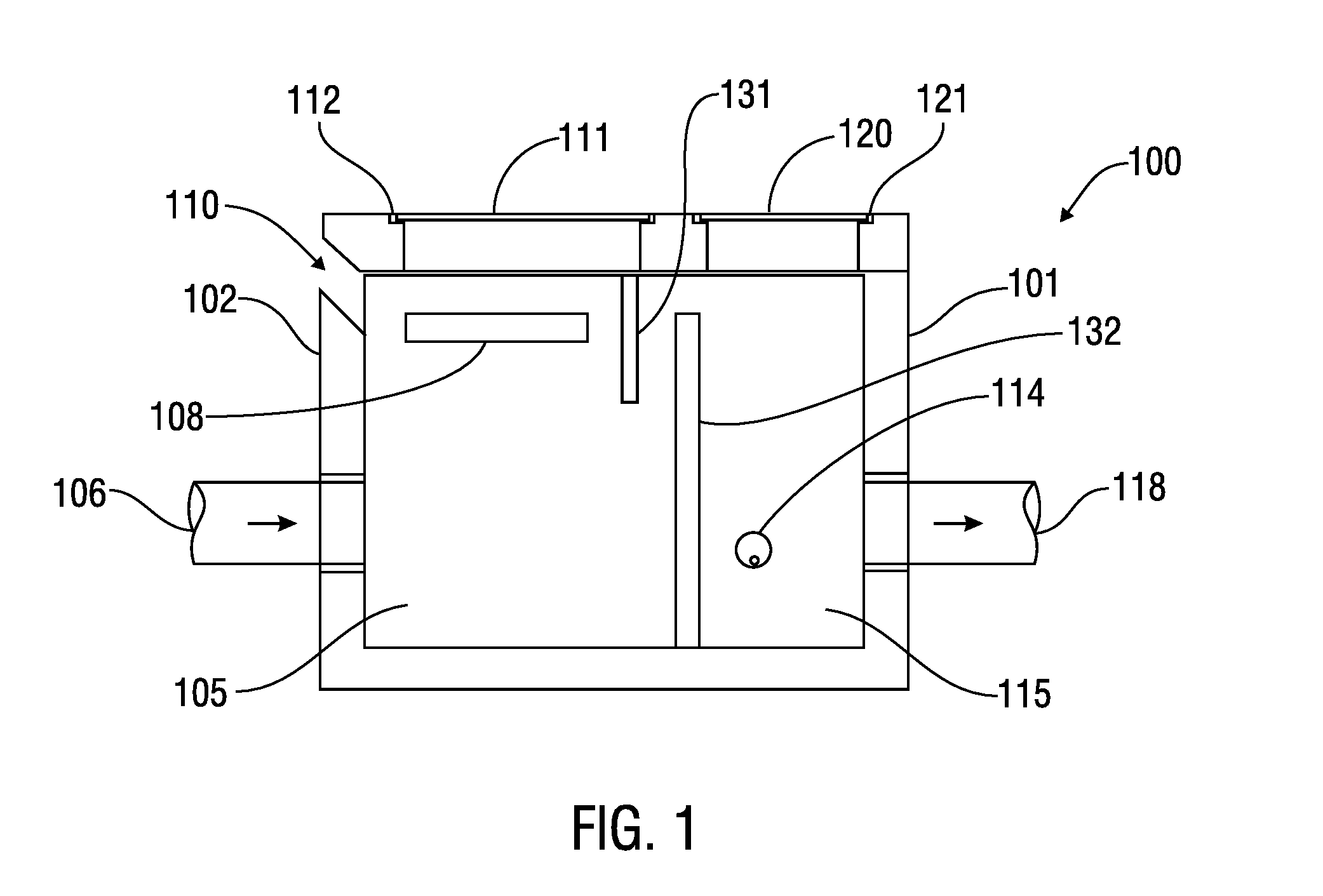
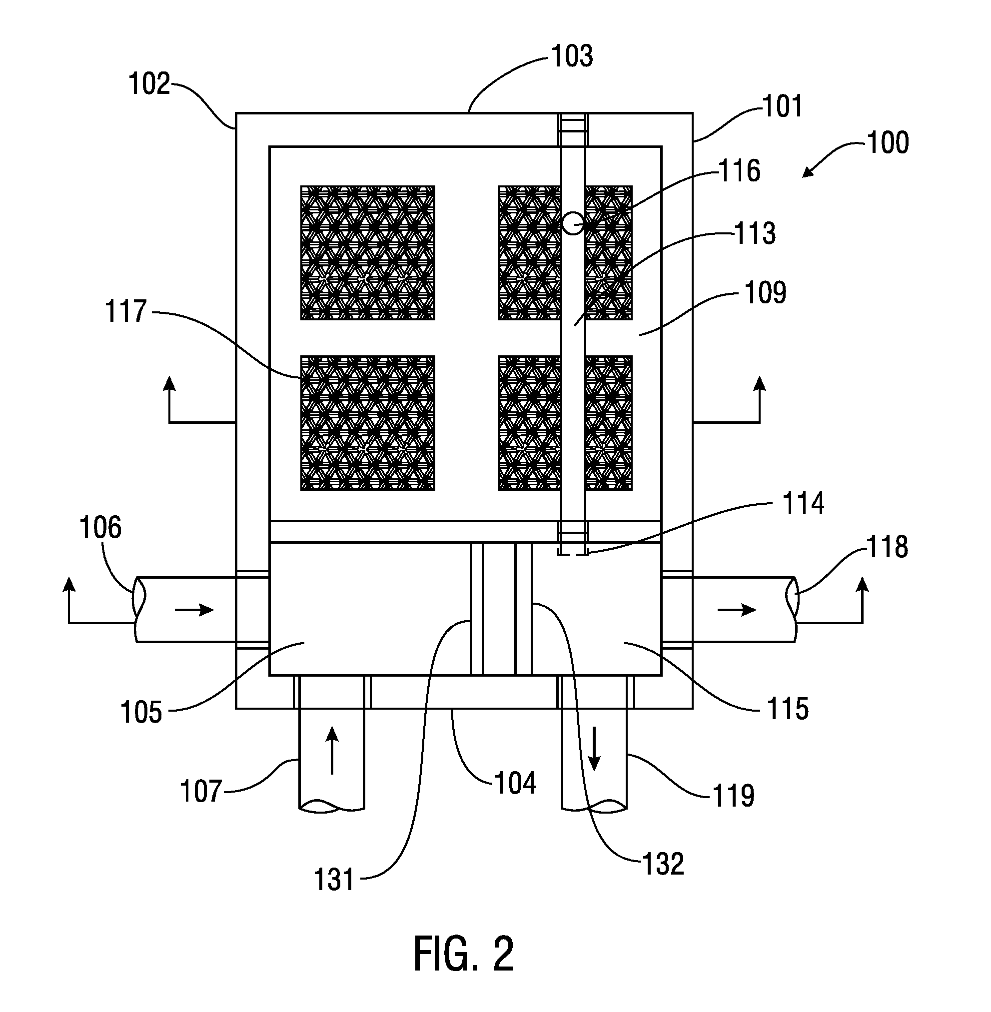
[0018]The present invention further provides an underground stormwater management system comprising a vault-shaped tree box filter. The tree box filter comprises four side walls and a bottom slab, which house an inlet gallery, a media area adjacent to the inlet gallery, an outlet gallery disposed below the inlet gallery. The tree box filter further comprises a recess in the bottom slab that defines a void space below an upper surface of the bottom slab. The bottom slab may comprise one or more openings or a solid floor slab. The recess is in fluid communication with underlying materials on which the tree box rests (e.g., base rock and / or surrounding soils) through one or more fluid conveying apparatuses disposed within the tree box filter. In one embodiment, the fluid conveying apparatus may comprise a substantially vertical pipe disposed within the outlet gallery. The substantially vertical pipe may be connected to an underdrain pipe in the media area. In another embodiment, the fluid conveying apparatus may comprise an opening in the media area below an upper surface of the bottom slab.

Problems solved by technology

The tree box filter's open bottom structure, however, limits the ability of the vault-shaped container to hold the bioretention media, gravel, and other container materials within the vault, before it is delivered and installed at a given site or landscape area.
Because separate site visits may be required to install the media, additional space, coordination, time, fuel, labor, and other resources may be required to transport the materials during delivery of the system.
However, because the high flow bypass is an external structure—externally added to the tree box or other bioretention system components—its incorporation with tree box filters requires additional space (to accommodate the external bypass structure), as well as additional design, manufacturing, installation, and maintenance costs.
The entrance of gross pollutants, such as trash, debris, floatables, and coarse sediments, are known to “clog” the system and thus reduce the efficiency.
It also increases the maintenance frequency of typical bioretention systems.

Method used


Image

  • Tree Box Filter with Hydromodification Panels
  • Tree Box Filter with Hydromodification Panels
  • Tree Box Filter with Hydromodification Panels

Examples


Embodiment Construction

[0026]As used herein, the terms “comprises,”“comprising,”“includes,”“including,”“has,”“having” or any other variation thereof, are intended to cover a non-exclusive inclusion. For example, a process, method, article, or apparatus that comprises a list of elements is not necessarily limited to only those elements but may include other elements not expressly listed or inherent to such process, method, article, or apparatus. Further, unless expressly stated to the contrary, “or” refers to an inclusive or and not to an exclusive or. For example, a condition A or B is satisfied by any one of the following: A is true (or present) and B is false (or not present), A is false (or not present) and B is true (or present), and both A and B are true (or present).

[0027]Also, use of the “a” or “an” are employed to describe elements and components of the invention. This is done merely for convenience and to give a general sense of the invention. This description should be read to include one or at ...


PUM

PropertyMeasurementUnit
sizeaaaaaaaaaa
elevationaaaaaaaaaa
permeableaaaaaaaaaa

Abstract

The invention provides structures, methods, and assemblies for bioretention systems, including tree box filters with substantially permeable panels integrated into a bottom portion of the tree box filter. The invention also provides methods and additional structures that are useful for managing stormwater flow and inhibiting the flow of pollutants, debris, and other contaminants into drainage systems.

Description

CROSS REFERENCE TO RELATED APPLICATIONS[0001]This application claims the benefit of U.S. Provisional Application No. 62 / 094,540 filed on Dec. 19, 2014, the subject matter of which is herein incorporated by reference in its entirety.FIELD OF THE INVENTION[0002]The present invention relates to assemblies and methods that are useful for the control of stormwater runoff and the removal of pollutants, debris, and other contaminants from stormwater runoff; and more specifically, bioretention assemblies and methods systems that are useful for managing stormwater flow and inhibiting the flow of pollutants, debris, and other contaminants into drainage systems.BACKGROUND OF THE INVENTION[0003]Tree box filters, which are also known as tree box planters, function as bioretention systems for managing and filtering stormwater runoff. They are a well-known Low Impact Design (“LID”) approach to mitigating the impacts of hydromodification, impervious surfaces, and the general alteration of flow, and...

Claims


Application Information

Patent Timeline
Patent Type & Authority Applications(United States)
IPC IPC(8): C02F3/32E03F1/00C02F3/04
CPCC02F3/327C02F3/043C02F2103/001E03F1/00C02F3/046E03F5/16C02F3/04C02F2203/006Y02W10/10
Inventor HOLTZ, JAMES FERGUSONDEMAREST, CHRIS RYAN
Owner OLDCASTLE PRECAST
Why Eureka
Try Eureka