Inspection Device And Method

a technology of inspection device and inspection method, applied in the direction of measuring device, optically investigating flaws/contamination, instruments, etc., can solve the problems of scrap further down the process, loss of yield in production process, and necessity to reject tape sections

Inactive Publication Date: 2016-06-23
XEROX CORP
View PDF26 Cites 4 Cited by
  • Summary
  • Abstract
  • Description
  • Claims
  • Application Information

AI Technical Summary

Problems solved by technology

Thickness variations in the transparent films and tapes can result in yield loss in production processes.
Such defects often result in the necessity to reject sections of tape.
Rejects that are missed can cause scrap further down the process.
This can result in loss that can be 100 times the cost of the tape itself.
Thickness variations can result from streaks down the length of the tape or from point defects.
Because the tape is transparent, and particularly if the tape has liners on it, it can be difficult to inspect for defects.
Neither back lighting nor overhead lighting is effective for visually inspecting these tapes.
Many defects elude detection, and inspection can be tedious and slow.
Proposed solutions to the problem have thus far been expensive and required considerable complex setup for a particular tape.

Method used


Image

  • Inspection Device And Method
  • Inspection Device And Method
  • Inspection Device And Method

Examples


example 1

[0037

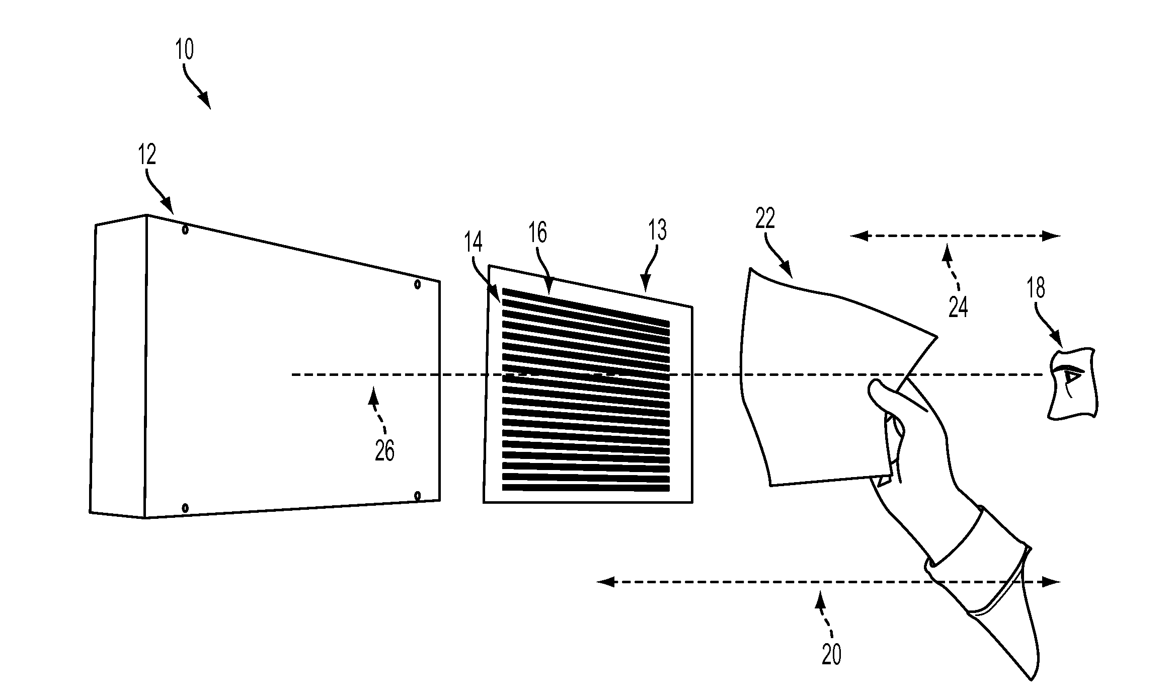
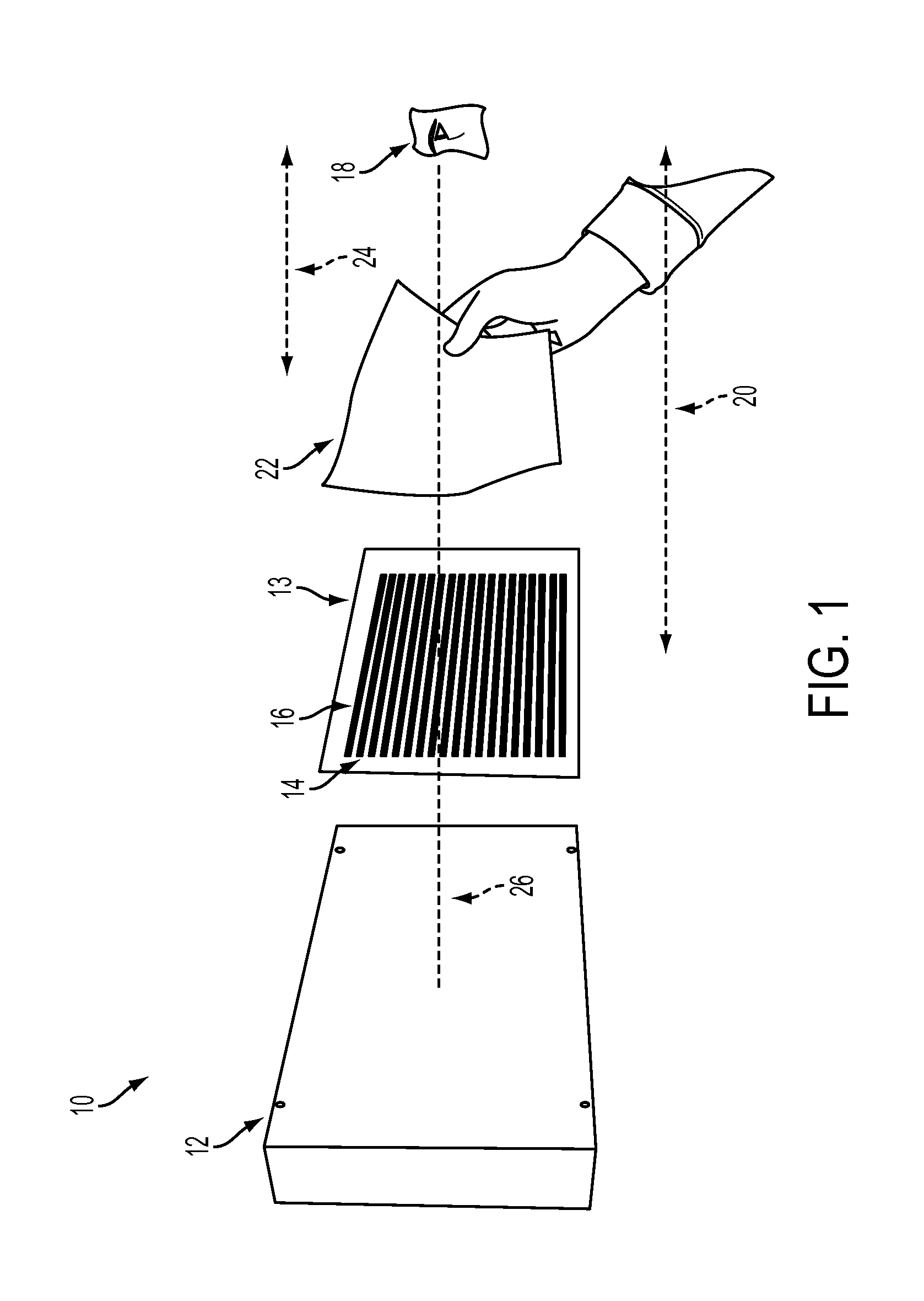
[0038]A production silicone PSA comprising an amber polyimide sheet with a nominal 0.0004 inch layer of clear silicone adhesive on either side, with clear polyester liners on both sides of the adhesive was used to demonstrate the instant embodiments. A bar pattern was generated using Microsoft® Word word processing software and printed on a transparency. The transparency was placed on an ordinary light box. Defects that were invisible on the light box and very difficult to see or undetectable in other lighting conditions became obvious.

[0039]FIG. 4 is an illustration showing previously invisible variation in adhesive thickness of a film, not visible with the naked eye or with use of an ordinary light box, which is now obvious with use of the present device and method. FIG. 4 shows how a vertical, invisible to the naked eye streak in the top, brown film disrupts the appearance of the angled bar pattern on the transparency. As shown in FIG. 4, transparent sample to be inspected 2...


PUM

PropertyMeasurementUnit
angleaaaaaaaaaa
thickaaaaaaaaaa
angleaaaaaaaaaa

Abstract

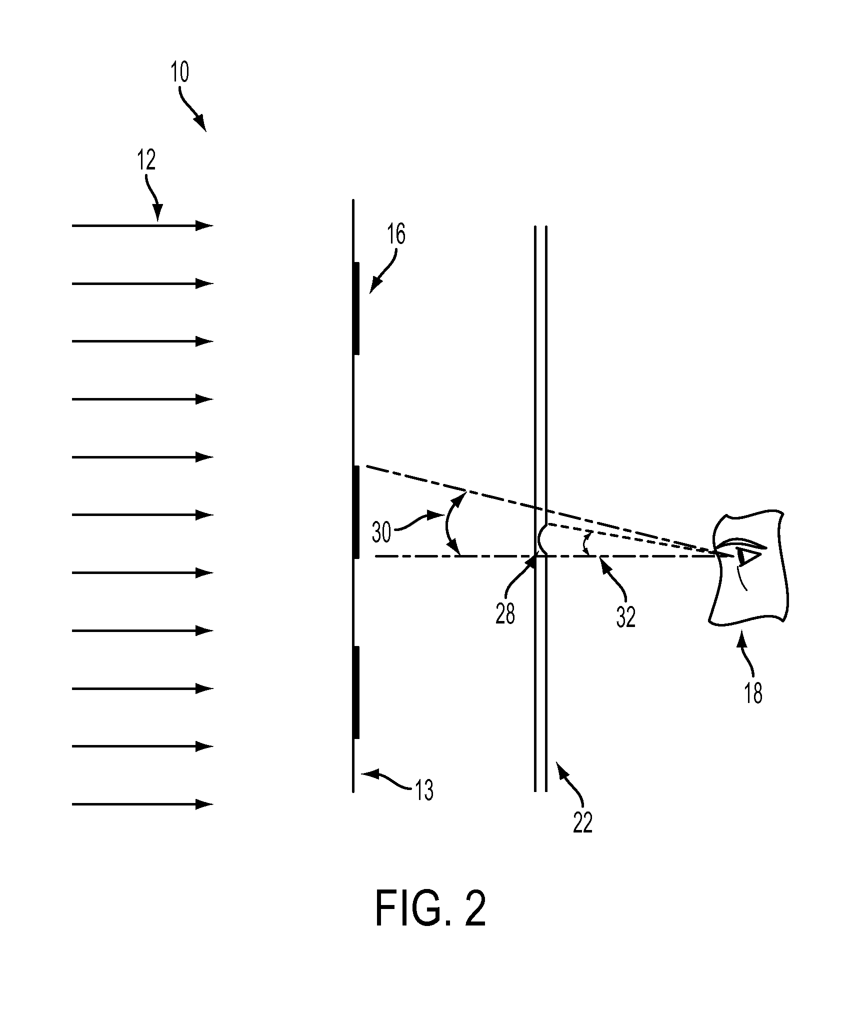
An inspection device including an illumination source emitting illumination that is divided into lighter and darker bands; a viewing system placed a first distance from the illumination source; a material to be evaluated placed a second intermediate distance between the illumination source and the viewing system on an imaginary line connecting the viewing system and at least some portion of the source of illumination. An inspection process including placing a material to be evaluated between an illumination source emitting illumination that is divided into lighter and darker bands and a viewing system placed a first distance from the illumination source; wherein the material to be evaluated is placed at a second intermediate distance between the illumination source and the viewing system, and on an imaginary line connecting the viewing system and illumination source; illuminating the material; and evaluating the material with the viewing system.

Description

BACKGROUND[0001]Disclosed herein is an inspection device and method. More particularly disclosed herein is an inspection device comprising an illumination source emitting illumination that is divided into lighter and darker bands; a viewing system placed a first distance from the illumination source; a material to be evaluated placed at a second intermediate distance between the illumination source and the viewing system, the material to be evaluated also placed on an imaginary line connecting the viewing system and at least some portion of the source of illumination.[0002]There are a large number of uses for transparent films and tapes. For example, transparent films and tapes are used to manufacture solid ink jet print heads. Thickness variations in the transparent films and tapes can result in yield loss in production processes. Such defects often result in the necessity to reject sections of tape. Rejects that are missed can cause scrap further down the process. This can result ...

Claims


Application Information

Patent Timeline
Patent Type & Authority Applications(United States)
IPC IPC(8): G01N21/958G01N21/88
CPCG01N21/958G01N21/8806G01N21/8803G01N2021/8832
Inventor HOUSTON, DAVID J.
Owner XEROX CORP
Why Eureka
Try Eureka