Conveyor chain

A technology of conveying chain and chain link, applied in the field of conveying chain, can solve the problem of high material cost and achieve the effect of reducing material cost

Active Publication Date: 2008-10-08
REXNORD FLATTOP EURO BV
View PDF1 Cites 4 Cited by
  • Summary
  • Abstract
  • Description
  • Claims
  • Application Information

AI Technical Summary

Benefits of technology

This technology reduces the size or weight of conveyor bodies parts without compromising their strengths. It achieves this through two ways: one uses less space on both sides for carrying loads compared to previous designs; another involves making it thinner than usual but still able to carry more objects effectively due to its small dimensions.

Problems solved by technology

Technically speaking, traditional types of flexible chains use bent rails or rollers along their tracks when they go around curves due to gravity forces acting upon them during operation. However, these systems require expensive materials and may lead to increased wear over time. Additionally, some designs involve adding extra parts called pivot joint assemblies (PCA) - specifically including secondary linkage rings placed next to the main part's middle section. These PCA allow for better movement within the system without increasing weight by reducing friction.

Method used


Image

  • Conveyor chain
  • Conveyor chain
  • Conveyor chain

Examples


Embodiment Construction

[0023] In these drawings, the same or corresponding parts are denoted by the same reference numerals. These figures are merely schematic representations of preferred embodiments of the invention given by way of non-limiting exemplary embodiments.

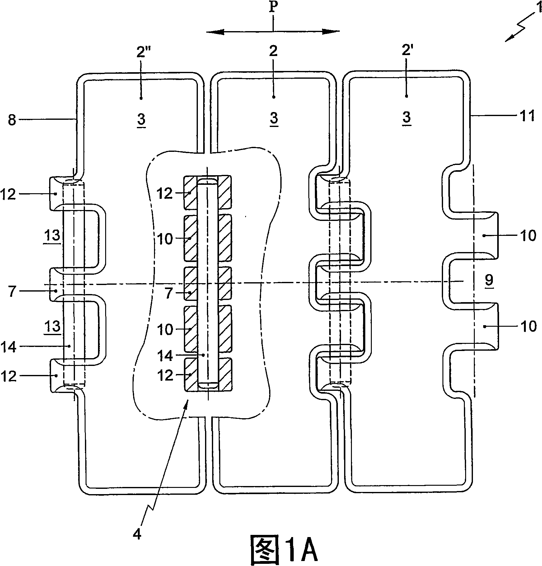
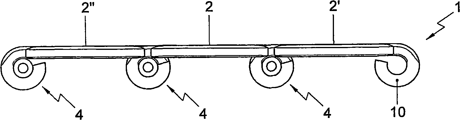
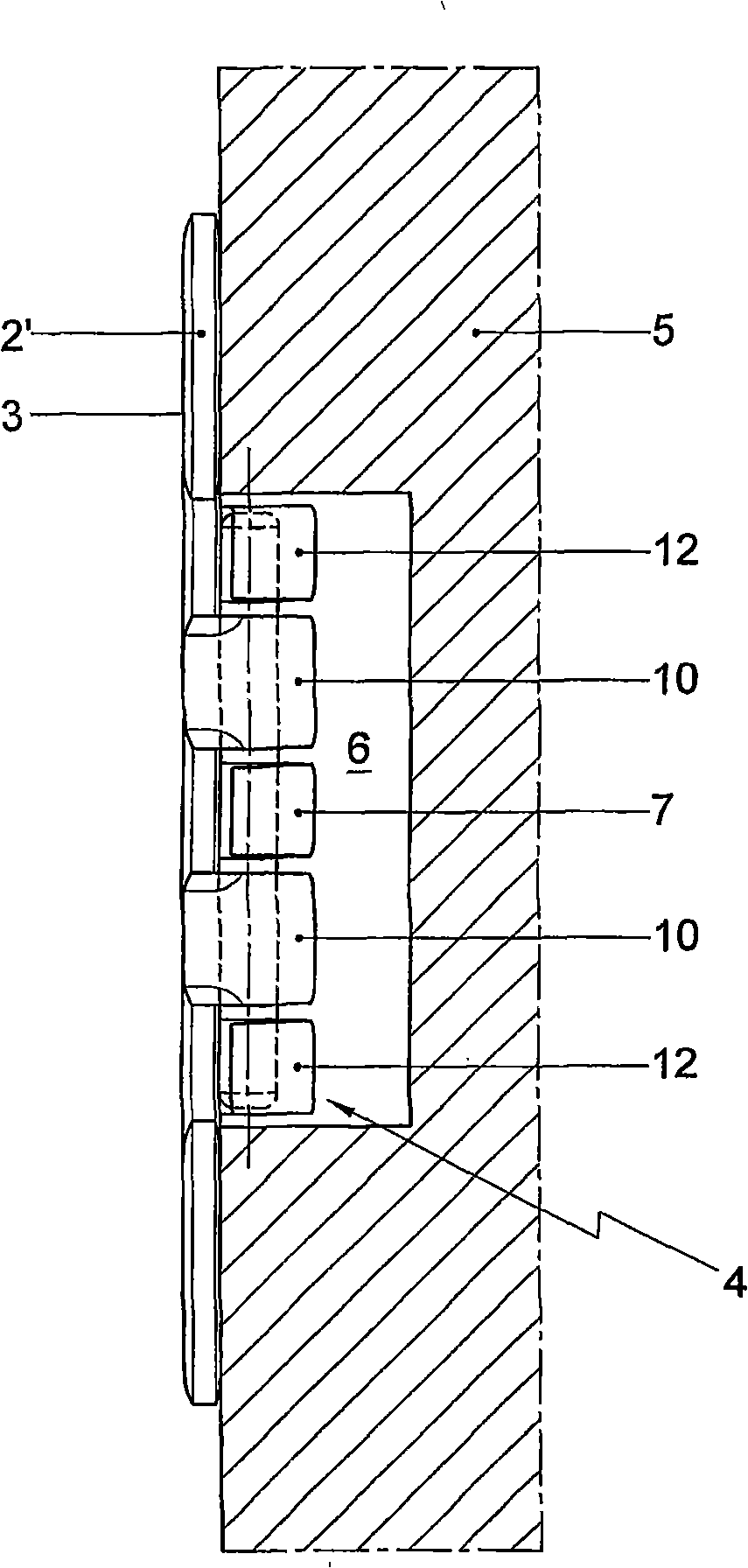
[0024] FIG. 1 shows a conveyor chain 1 comprising a series of sheet metal links 2 . Each chain link 2 is respectively provided with a substantially rectangular transmission body part 3 and a hinge assembly 4 located below the transmission body part 3 . In use, the conveyor chain 1 is intended to move along the conveyor track 5 in the conveying direction indicated by the arrow P. The transfer rail 5 supports the transfer body part 3 and is provided with a groove 6 for guiding the hinge assembly 4 therein.

[0025] The sheet metal links are stamped from sheet metal in a manner known to those skilled in the art, while forming the articulating ring. In this exemplary embodiment, the chain links are produced from ferritic-pearlitic st...


PUM

PropertyMeasurementUnit
Thicknessaaaaaaaaaa
Diameteraaaaaaaaaa
Thicknessaaaaaaaaaa

Abstract

A conveyor chain (1) , comprising a series of sheet metal chain links (2) which are each provided with a basically rectangular conveying body part (3) and with a hinge assembly (4) , which hinge assembly comprises a centrally located hinge loop (7) and comprises a pair of hinge loops (10) spaced apart with an intermediate distance (9) on the opposite longitudinal side of the chain link, wherein the central loop is located in the intermediate space of a successive module(2'), wherein the hinge assembly(4) further comprises two auxiliary hinge loops (12) , wherein the cooperating hinge loops ofsuccessive modules are connected by means of hinge pins (14) , the thickness of the sheet metal of the conveying body part being between approximately 2.0 mm and approximately 2.8 mm, and wherein thediameter of the hinge pin is between approximately 3.0 and 5.0 mm .

Description


Claims


Application Information

Patent Timeline
Owner REXNORD FLATTOP EURO BV
Why Eureka
Try Eureka