Stereoscopic display device

a display device and stereoscopic technology, applied in the direction of instruments, color television details, electrical devices, etc., can solve the problems of insufficient visibility of 3d moiré, difficulty in eliminating the processing variation of about several m as the shape precision, and the observer's sense of discomfor

Active Publication Date: 2016-06-23
TIANMA MICRO ELECTRONICS CO LTD
View PDF3 Cites 4 Cited by
  • Summary
  • Abstract
  • Description
  • Claims
  • Application Information

AI Technical Summary

Benefits of technology

[0039]As an exemplary advantage according to the invention, the present invention can achieve a fine stereoscopic display property even with a naked-eye type stereoscopic display device which employs a display panel with narrow-pitch sub-pixels or a display panel with a large number of pixels.

Problems solved by technology

When a part, which is not intended to be viewed, in that region is viewed by an observer in an expanded manner due to the light-ray control module, a sense of discomfort is given to the observer.
However, there is such an issue that the visibility of 3D moiré cannot be decreased sufficiently even when the above-described related techniques are used.
Considering the currently used typical materials and manufacturing devices for photolithography, it is difficult to completely eliminate processing variation of about several μm as the shape precision.
Further, in order to control the processing variation to be less than the order of sub-μm level, expensive materials and manufacturing devices are required.
Thus, it is difficult to provide inexpensive stereoscopic display devices.
Therefore, in terms of 3D moiré, it is advantageous to have a smaller angle θ. However, when the angle θ is too small, the overlapping section of the sub-pixels becomes extremely large so that the 3D crosstalk property tends to be deteriorated.
However, in that case, even when the correction pattern is added, the processing precision variation cannot be absorbed sufficiently.
Not only that, there still remains such an issue that the correction pattern itself cannot be disposed or that the correction pattern cannot function when high definition is advanced.
However, this means to shift the focal distance intentionally, so that the stereoscopic display property typically 3D crosstalk is worsened.
When variation in the lens-pixel distance is large, defocusing is worsened further so that the 3D crosstalk property is deteriorated greatly.

Method used


Image

  • Stereoscopic display device
  • Stereoscopic display device
  • Stereoscopic display device

Examples


first exemplary embodiment

Operations and Effects

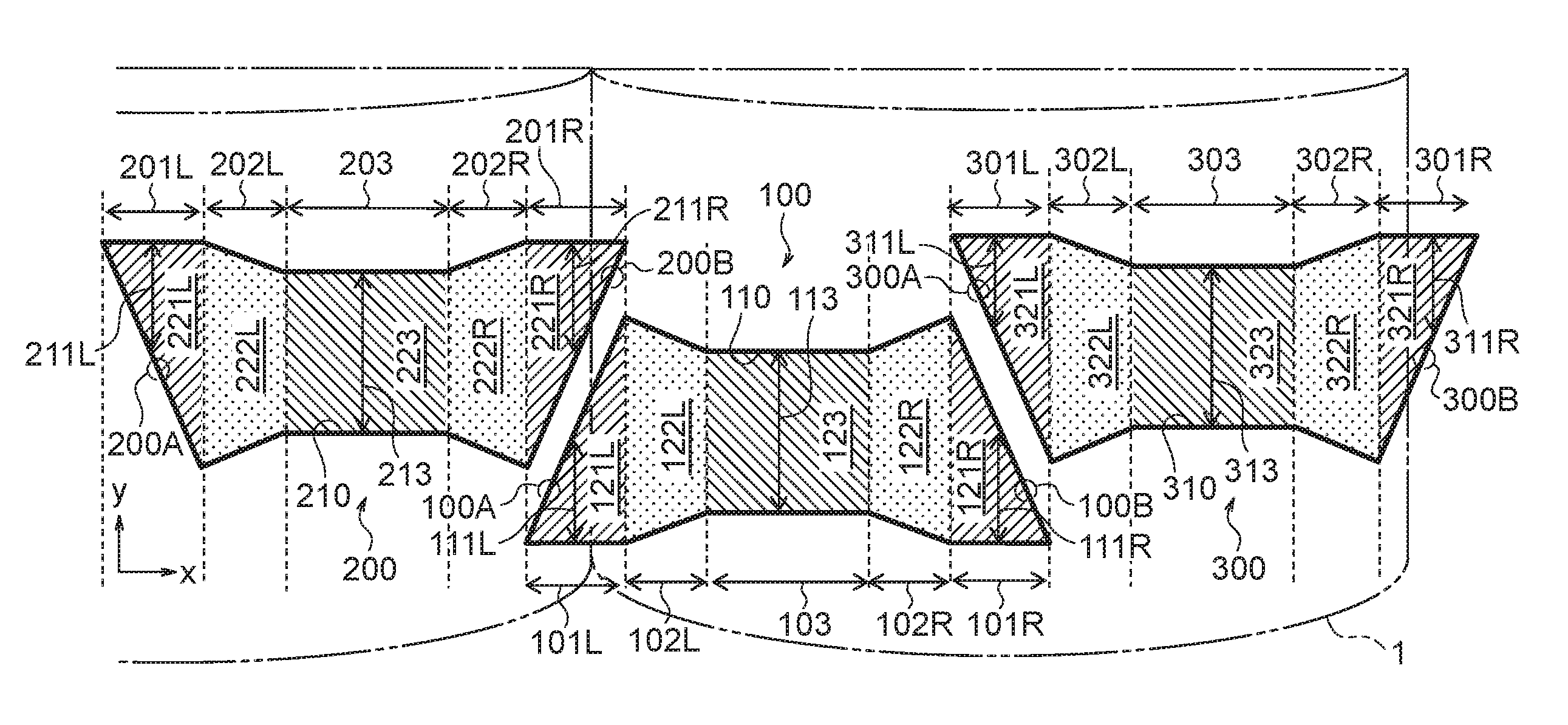
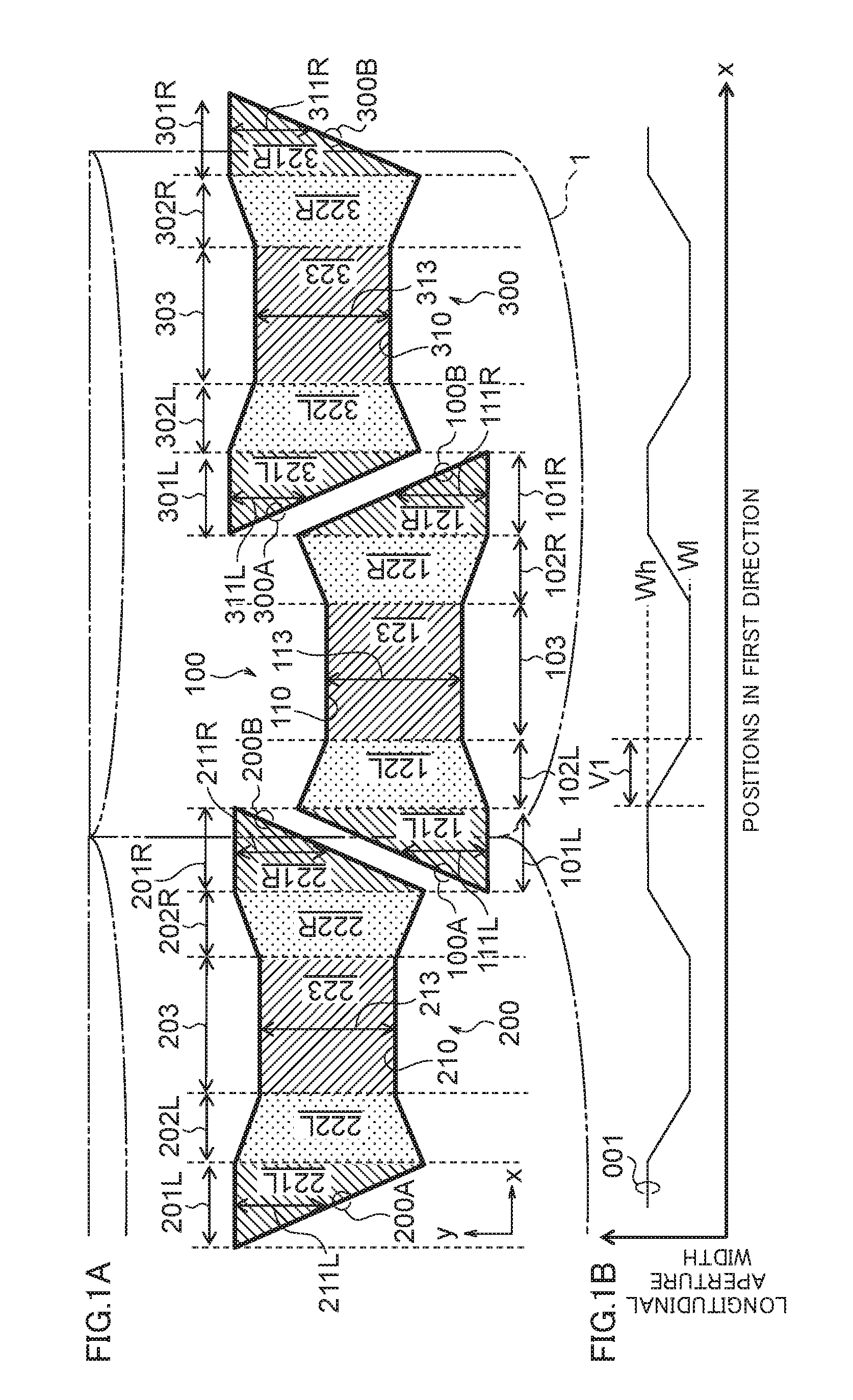
[0100]Examples 1 to 3 described above employ the ideal sub-pixel structures. A case where a rounded corner is generated in the aperture part in Example 1 will be described by referring to FIG. 4A. In FIG. 4A, shown are the aperture parts 110, 210 (broken lines) of the ideal sub-pixels shown in FIG. 1A and the aperture parts 110a, 210a of the sub-pixels 100a, 200a with the rounded corners. As in the case of the ideal aperture part 110 (210), there are three sections, i.e., the aperture width constant section 103a (203a), the aperture width fluctuating section 102aL (202aR), and the overlapping section 101aL (201aR) in the aperture part 110a (210a).

[0101]Compared to the ideal aperture part 110 (210), the overlapping section 101aL (201aR) in the aperture part 110a (210a) is reduced due to rounding of the corner and, at the same time, the aperture width fluctuating section 102aL (202aR) is expanded for that. FIG. 4B shows the state where the total value of the long...

second exemplary embodiment

[0113]A second exemplary embodiment will be described by referring to FIG. 8A. Sub-pixels 600, 700, and 800 of the second exemplary embodiment are arranged along the first direction x. The unit lenses of the lens 1 as the light-ray control modules are disposed at the positions corresponding to a pair of sub-pixels 600, 800, and arranged repeatedly along the first direction x.

[0114]The aperture width constant region existed in the first exemplary embodiment does not exist in the aperture part 610 (710, 810) of the sub-pixel 600 (700, 800) of the second exemplary embodiment. There are two overlapping regions 621L (721L, 821L) and 621R (721R, 821R) in the aperture part 610 (710, 810). Further, there is an aperture width fluctuating region existing between the two overlapping regions. The aperture width fluctuating region is divided into two aperture width fluctuating regions 622L (722L, 822L) and 622R (722R, 822R).

[0115]That is, the aperture part 610 includes: the overlapping region 62...

third exemplary embodiment

Summary

[0126]Note here that the distance between the maximum value and the minimum value of the aperture position in the second direction of a single sub-pixel is defined as an optical longitudinal aperture section. That is, the maximum value of the difference between the position at one end of the aperture part in the second direction and the position at the other end of the aperture part in the second direction is defined as “longitudinal aperture section”. In the aperture part 901UL of Comparative Example shown in FIG. 10A, the difference between the position at one end 904 in the second direction y and the position at the other end 905 in the second direction y is the longitudinal aperture section 903. In the aperture part 911UL of Example 1 shown in FIG. 11A, the difference between the position at one end 914 in the second direction y and the position at the other end 915 in the second direction y is the longitudinal aperture section 913. In the aperture part 921UL of Example 2...


PUM


Abstract

To provide a naked-eye type stereoscopic display device which can achieve a fine stereoscopic display property while achieving high-definition display and high yield. Aperture parts of sub-pixels neighboring to a first direction include overlapping regions which overlap in a second direction and a non-overlapping region which does not overlap. Provided that a width of the aperture part in the second direction is defined as a longitudinal aperture width, the non-overlapping region includes an aperture width fluctuating region where the longitudinal aperture width changes continuously from roughly a center of the aperture part towards both ends of the first direction, respectively. The sum of the longitudinal aperture widths of the two overlapping regions overlapping with each other at a same position in the first direction is larger than the longitudinal aperture width in roughly the center of the aperture part.

Description

CROSS-REFERENCE TO RELATED APPLICATION[0001]This application is based upon and claims the benefit of priority from Japanese patent application No. 2014-258568, filed on Dec. 22, 2014, and Japanese patent application No. 2015-202118, filed on Oct. 13, 2015, the disclosure of which is incorporated herein in its entirety by reference.BACKGROUND OF THE INVENTION[0002]1. Field of the Invention[0003]The present invention relates to a stereoscopic display device which provides stereoscopic images to observers with naked eyes.[0004]2. Description of the Related Art[0005]A naked-eye type stereoscopic display device does not require any special eyeglasses, so that the observer can enjoy stereoscopic images readily. With personal mobile terminals such as mobile phones, smartphones, and feature phones and household display devices such as television set receivers, such techniques for achieving in naked-eye type stereoscopic display are being developed rapidly.[0006]The naked-eye type stereoscop...

Claims


Application Information

Patent Timeline
Patent Type & Authority Applications(United States)
IPC IPC(8): H04N13/04
CPCH04N13/0418G02B30/27H04N2213/001
Inventor ASAI, TAKUYASHIGEMURA, KOJI
Owner TIANMA MICRO ELECTRONICS CO LTD
Why Eureka
Try Eureka