Stereoscopic display device and display control method thereof

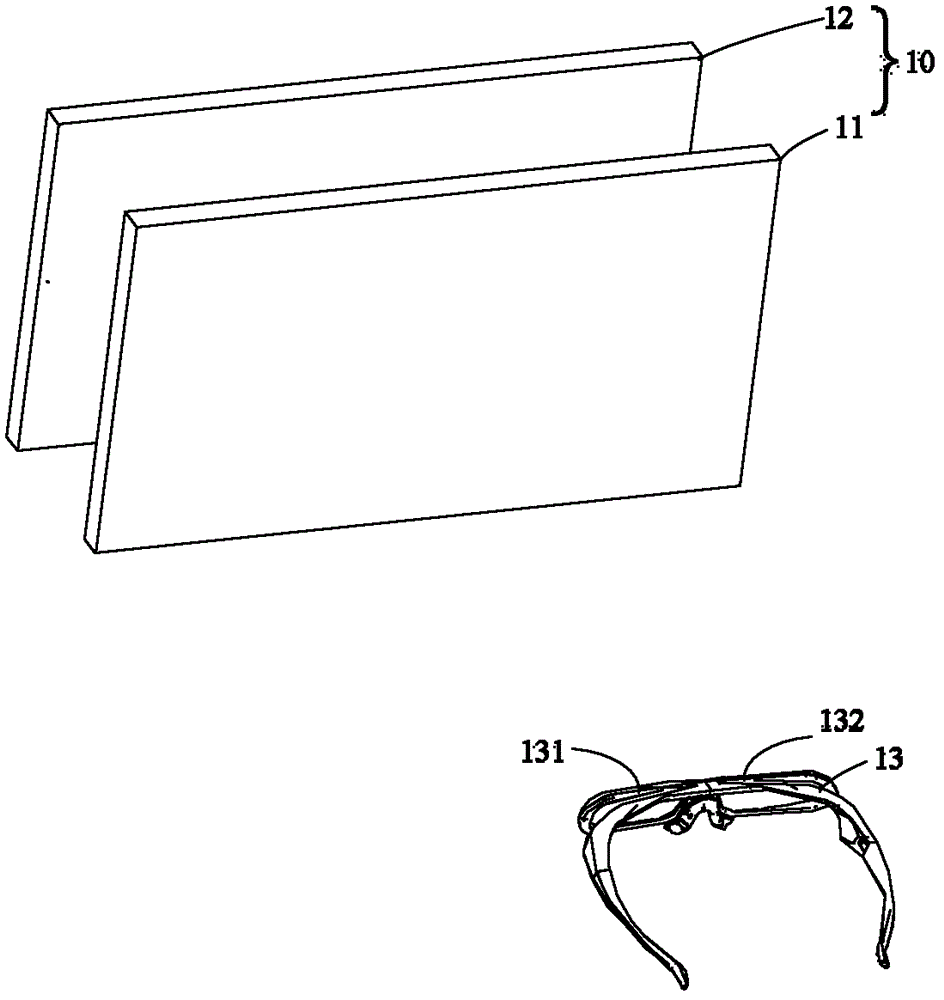
A technology for a stereoscopic display device and a display area, which is applied to stereoscopic systems, static indicators, optics, etc., can solve the problems of late opening and closing time of the left eye lens 131, affecting the stereoscopic display effect, and seeing afterimages, etc., so as to improve the stereoscopic Display effect, increase the opening maintenance time, reduce the effect of crosstalk

Inactive Publication Date: 2015-11-25
TCL CHINA STAR OPTOELECTRONICS TECH CO LTD
View PDF4 Cites 0 Cited by
  • Summary
  • Abstract
  • Description
  • Claims
  • Application Information

AI Technical Summary

Problems solved by technology

Cooperate with the signal drive of the whole area S1, S2, S3, S4 and S5, because the opening and closing time of the left eye lens 131 is late, the driving signal of the area S1 has been changed from the left eye frame to the next signal right eye frame, because the liquid crystal pixel There is a reaction time L0, which causes both left-eye frame and right-eye frame to exist in area S1, and afterimages will be seen in area S1
In addition, the opening time of the left-eye glass 131 is relatively early, and at the same time it provides driving signals to regions S1, S2, S3, S4, and S5. Due to the response time L0 of the liquid crystal pixels, regions S1, S2, S3, S4, and S5 will be affected to varying degrees. Influenced by a right-eye frame, there will be afterimages
[0005] Based on the above, in the prior art stereoscopic display device, there is crosstalk between left and right eye signals, which causes afterimages and affects the stereoscopic display effect.

Method used


Image

  • Stereoscopic display device and display control method thereof
  • Stereoscopic display device and display control method thereof
  • Stereoscopic display device and display control method thereof

Examples


Embodiment Construction

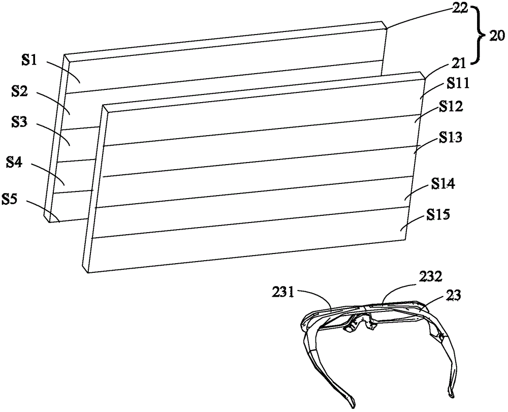
[0024] See image 3 , image 3 It is a schematic diagram of a preferred embodiment of the stereoscopic display device of the present invention. Such as image 3 As shown, the stereoscopic display device of the present invention includes a liquid crystal display 20 and shutter glasses 23 . The liquid crystal display 20 further includes a liquid crystal display panel 21 and a backlight module 22 . Wherein, the liquid crystal display panel 21 is disposed between the backlight module 22 and the shutter glasses 23 , and is illuminated by the backlight module 22 .

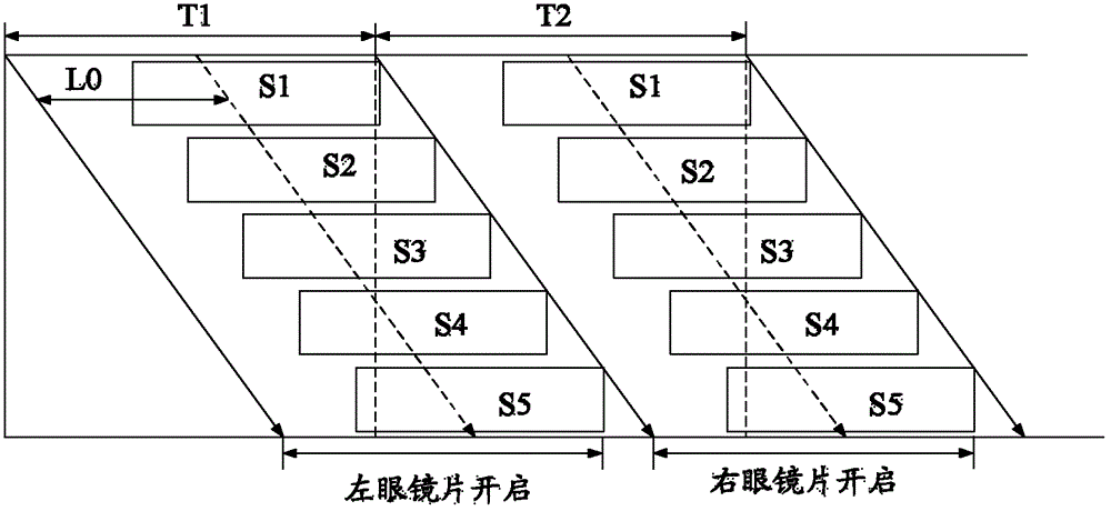
[0025] The liquid crystal display panel 21 is used to alternately display the left-eye frame and the right-eye frame. Wherein, the liquid crystal display panel 21 is divided into a plurality of display areas distributed sequentially from two sides to the middle. In this embodiment, the liquid crystal display panel 21 is divided into five display areas. The five display areas are respectively display areas S11, S12, ...


PUM


Abstract

Provided in the present invention are a stereoscopic display device and a display control method therefor. Multiple display areas are sequentially driven in a scheme of scanning from two sides towards the center of a liquid crystal display panel, multiple backlight units are controlled to sequentially activate in the order of running from the center towards the two sides thereby matching the scheme of scanning the multiple display areas, thus allowing each backlight unit to activate only after a drive signal of an image frame is received by the corresponding display area and after a liquid crystal pixel of the display area has reacted, and to shutdown when the display area starts to receiving the drive signal of another image frame. Through this scheme, the present invention allows for increased activation duration of the backlight units, and for reduced crosstalk generated by the stereoscopic display device, thus reducing the generation of image retention, improving stereoscopic display effects, and enhancing user experience results.

Description

technical field [0001] The invention relates to the field of display technology, in particular to a stereoscopic display device and a display control method thereof. Background technique [0002] In recent years, stereoscopic display technology has developed rapidly and has become a research hotspot in the industry. Stereoscopic display technology has important applications in medical, advertising, military, exhibition, games and other fields. see figure 1 , figure 1 is a schematic diagram of a stereoscopic display device in the prior art. Such as figure 1 As shown, the stereoscopic display device mainly includes a liquid crystal display 10 and shutter glasses 13 . The liquid crystal display 10 mainly includes a liquid crystal display panel 11 and a backlight module 12 . The liquid crystal display panel 11 can alternately display left-eye images and right-eye images under the condition that the backlight module 12 provides illumination. [0003] The shutter glasses 13...

Claims


Application Information

Patent Timeline
Patent Type & Authority Patents(China)
IPC IPC(8): G02F1/133G02B27/22H04N13/04
CPCG02B27/2264H04N13/0438G02B30/24H04N13/341
Inventor 康志聪
Owner TCL CHINA STAR OPTOELECTRONICS TECH CO LTD
Why Eureka
Try Eureka