
Fueling device

a fueling device and a technology for fueling, applied in the direction of liquid handling, packaging goods, transportation and packaging, etc., can solve the problems of deteriorating the mounting property of the cover member and the inability to so as to increase the wall thickness of the cover member, and suppress the expansion and deformation of the cover member

Active Publication Date: 2016-06-30
TOYODA GOSEI CO LTD
View PDF25 Cites 5 Cited by
  • Summary
  • Abstract
  • Description
  • Claims
  • Application Information

AI Technical Summary

Benefits of technology

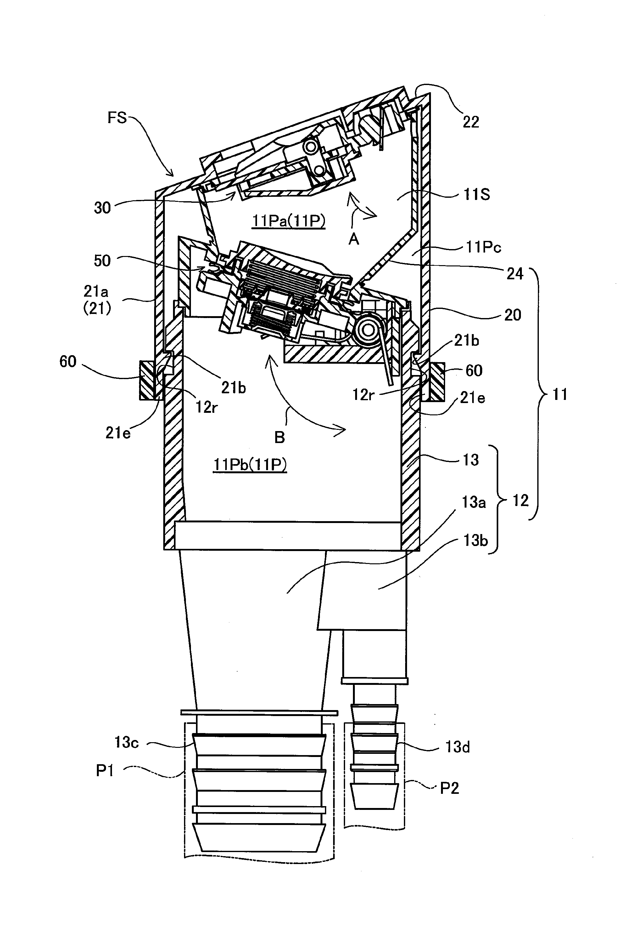
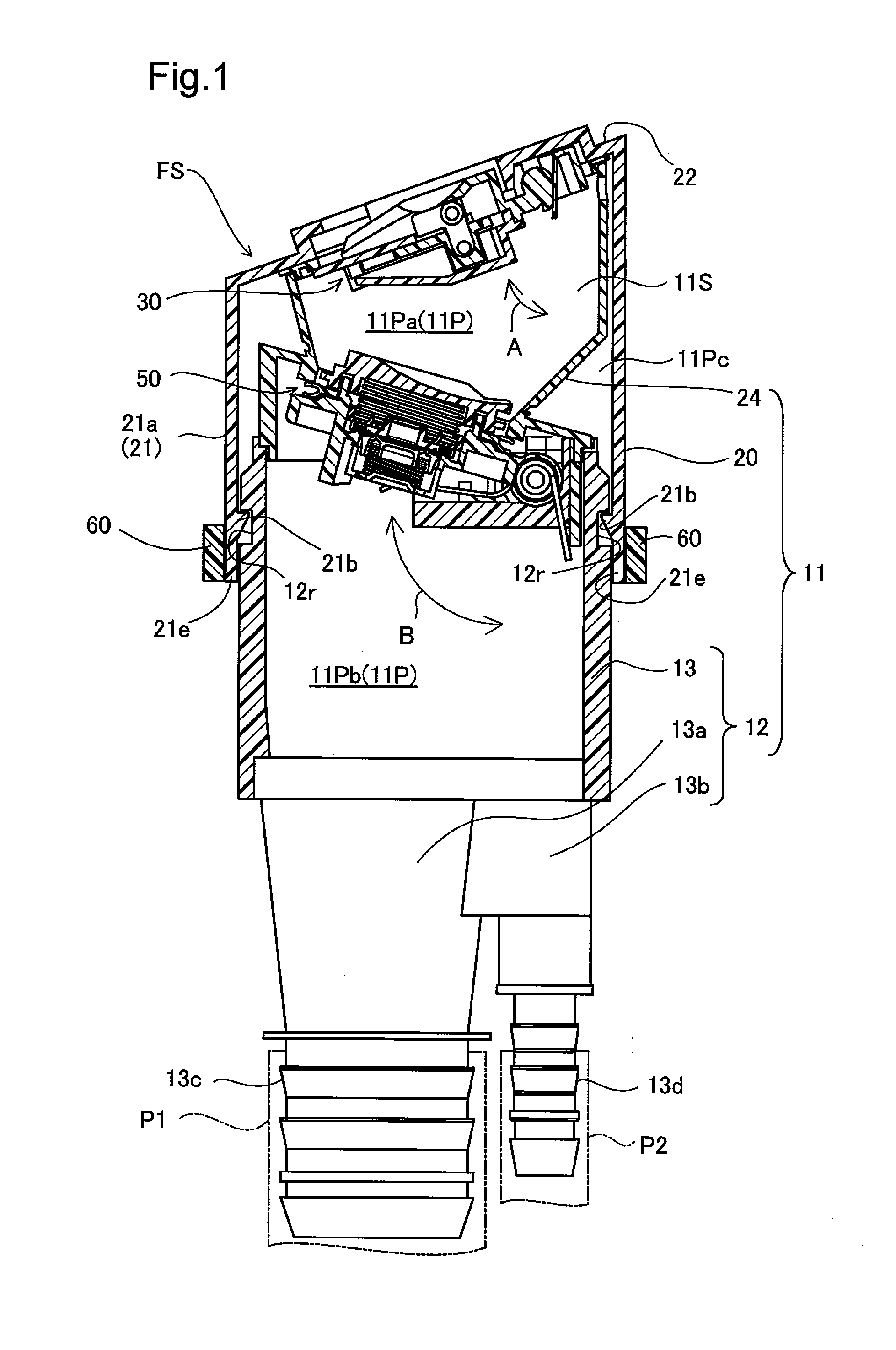
The fueling device described in this patent has a restraint portion that prevents the cover member from expanding and deforming when a load is applied from a fueling nozzle. This prevents the cover member from separating from the filler neck and maintains its mounting property. The restraint portion can be located to restrain the cover member in the area where it is engaged with the filler neck or in the extension portion of the cover member. This ensures effective engagement and prevents separation of the cover member from the filler neck. Overall, the fueling device prevents expansion and deformation of the cover member to enhance its reliability and performance.

Problems solved by technology

This, however, also suppresses expansion and deformation of the cover member during mounting of the cover member to the filler neck and thus deteriorates the mounting property of the cover member.
Accordingly, increasing the wall thickness of the cover member is not the practical solution.

Method used


Image

  • Fueling device
  • Fueling device
  • Fueling device

Examples


second embodiment

[0032]The following describes other embodiments. FIG. 3 is a cross sectional view illustrating the configuration of a restraint member 60 in a fueling device FS according to a This embodiment is characterized by the two-part configuration of the restraint member 60. As illustrated, the restraint member 60 includes a first restraint member 61 and a second restraint member 62. The first restraint member 61 and the second restraint member 62 respectively have circular arc portions in arc shape to surround the respective semicircular areas of the filler neck 12 (or more specifically, the cylindrical portion 13) and have flat plate portions 61p and 62p extended from the respective ends of the circular arc portions. The first restraint member 61 has an engagement hole 64 formed in one flat plate portion 61p. The second restraint member 62 has an engagement piece 65 provided in one flat plate portion 62p to be fit in and engaged with the engagement hole 64. In the state that the engagemen...

fourth embodiment

[0037]FIG. 5 is a cross sectional view illustrating the configuration of a restraint member 60 in the configuration of main part of a fueling device FS according to a This embodiment is characterized by the configuration of the restraint member 60 that is provided as a one-part member and is formed in an arc shape having open ends. This restraint member 60 is expandable on the open ends side. In the process of mounting the restraint member 60 to the restraint member mounting recess 21ar shown in FIG. 4, the open ends side of the restraint member 60 is expanded to allow for insertion of the cover member 20 and is subsequently returned to the original state after the insertion. The restraint member 60 accordingly restrains the cover member 20 to the outer circumferential wall of the cylindrical portion 13 of the filler neck 12 in the restraint member mounting recess 21ar of the cover member 20 or in other words, in the area from the engagement extension portion 21e to the engagement ...


PUM

PropertyMeasurementUnit
Timeaaaaaaaaaa
Massaaaaaaaaaa
Dynamic viscosityaaaaaaaaaa

Abstract

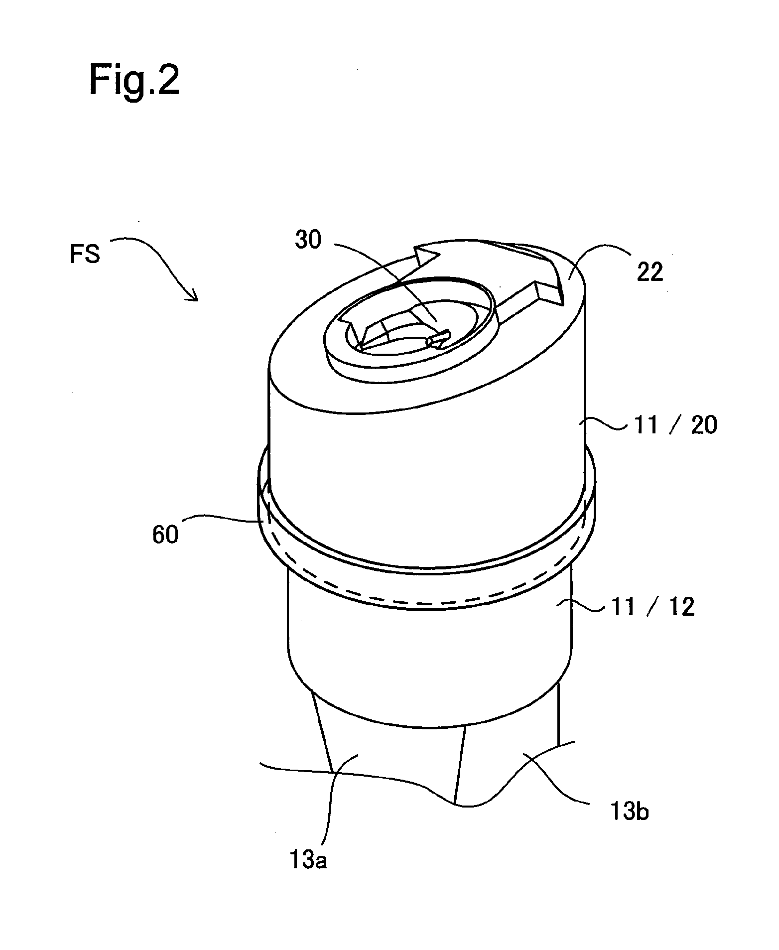
A fueling device comprises a filler neck that is configured to form a fuel flow path, a cover member, and a restraint portion. An engagement projection provided as an engagement portion of the cover member is engaged with an engaged recess provided as an engaged portion of the filler neck, so that the cover member is mounted to the filler neck on an opening side of the fuel flow path. The restraint portion is configured to restrain the cover member including an engagement extension portion downstream of the engagement projection in the fuel flow path to an outer circumferential wall of the filler neck. This configuration suppresses expansion and deformation of the cover member and avoids separation of the cover member from the filler neck, while maintaining the mounting property of the cover member.

Description

CROSS-REFERENCE TO RELATED APPLICATION[0001]The present application claims priority from Japanese application P2014-263707 filed on Dec. 26, 2014, the content of which is hereby incorporated by reference into this application.BACKGROUND[0002]1. Field[0003]The invention relates to a fueling device.[0004]2. Description of the Related Art[0005]In a generally known configuration of a fueling device, when a fueling nozzle used for fueling is pressed into the fueling device, a valve element is opened to start fueling from the fueling nozzle (for example, JP 2013-71504A). In this fueling device, a resin cover member that is configured to protect the periphery of the valve element on a fill port side from dust and rainwater is mounted to a filler neck that is configured to form a flow path connecting to a fuel tank on the fill port side. In the process of mounting the cover member to the filler neck, an engagement portion of the cover member is engaged with an engaged portion that is provid...

Claims


Application Information

Patent Timeline
IPC IPC(8): B60K15/04
CPCB60K2015/047B60K15/04B60K2015/0461
Inventor KITO, HIROAKIHIRAMATSU, YOSHINARI
Owner TOYODA GOSEI CO LTD
Learn More