Vehicle door

a technology for vehicles and doors, applied in the field of vehicles, can solve the problems of difficult deformation plastically of the first dividing element toward the interior of the vehicle compartment, and achieve the effects of reducing the impact force transmitted from the door beam to the door lock section, reliably releasing the locking state, and reducing the impact energy applied from the front of the vehicle body

Inactive Publication Date: 2005-09-13
HONDA MOTOR CO LTD
View PDF4 Cites 19 Cited by
  • Summary
  • Abstract
  • Description
  • Claims
  • Application Information

AI Technical Summary

Benefits of technology

[0009]The collision force acting on the door from ahead of the vehicle body is transmitted, as a compression force acting on the door beam in the longitudinal direction thereof, from a region at and around the hinge of the door frame, via the door beam, to a region at and around the door lock section. If the collision force acting on the door beam is greater than predetermined intensity, each end portion moves rearward with respect to the end portion provided in overlapping relation thereto by the predetermined distance to thereby absorb the collision energy. Therefore, the collision energy applied from ahead of the vehicle body can be alleviated significantly by being absorbed promptly and sufficiently by the door beam. Further, because the collision energy applied from ahead of the vehicle body is absorbed by the door beam, an impact force transmitted from the door beam to the door lock section can be greatly reduced. Since the door lock section is subjected to only a small impact force, it can still remain in its predetermined state where the door lock can be released as desired. Therefore, even after the door has undergone the impact force, it is possible to operate the door lock section to reliably release the locking state.
[0010]Preferably, the dividing members comprise a first dividing member positioned closer to the hinge and a second dividing member positioned closer to the door lock section, and mutually-joined areas of the end portions are located near the hinge, and the first dividing member is located closer to the interior of a vehicle compartment than the second dividing member. The mutually-joined dividing areas of the end portions are located near the hinge, namely near the high-rigidity door frame. The first dividing element has only a small length from the hinge to the dividing area, and thus it has greater rigidity than the second dividing element. Because the higher-rigidity first dividing element is located closer to the interior of the vehicle compartment, the first dividing element is more difficult to deform plastically toward the interior of the vehicle compartment. As a consequence, it is possible to suppress plastic deformation of the second dividing element toward the interior of the vehicle compartment. In this way, there can be minimized plastic deformation, toward the interior of the vehicle compartment, of the first and second dividing elements having undergone a collision force from ahead of the vehicle body. Thus, it becomes possible to lessen an impact applied to the passenger and thereby even further enhance the passenger protecting performance of the door.

Problems solved by technology

Because the higher-rigidity first dividing element is located closer to the interior of the vehicle compartment, the first dividing element is more difficult to deform plastically toward the interior of the vehicle compartment.

Method used


Image

  • Vehicle door
  • Vehicle door
  • Vehicle door

Examples


Embodiment Construction

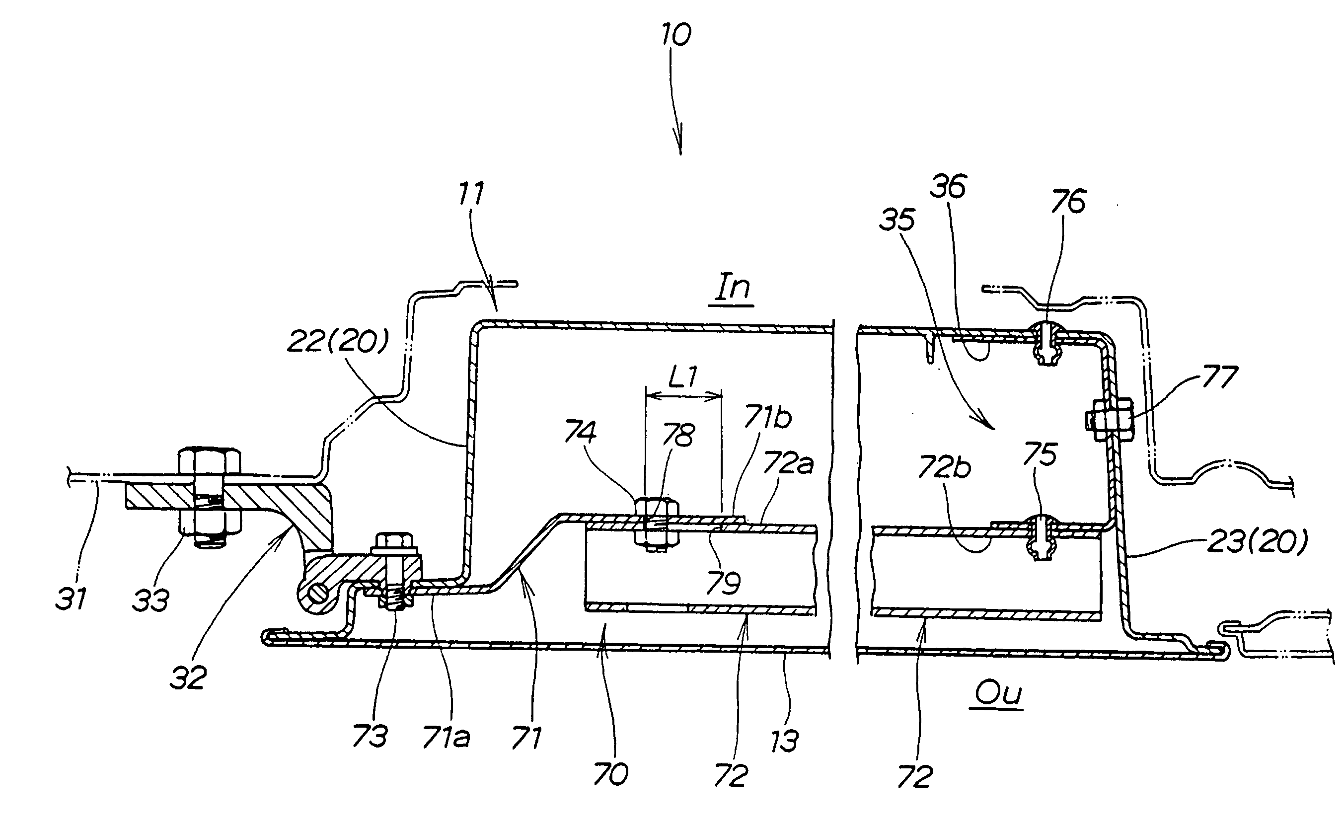
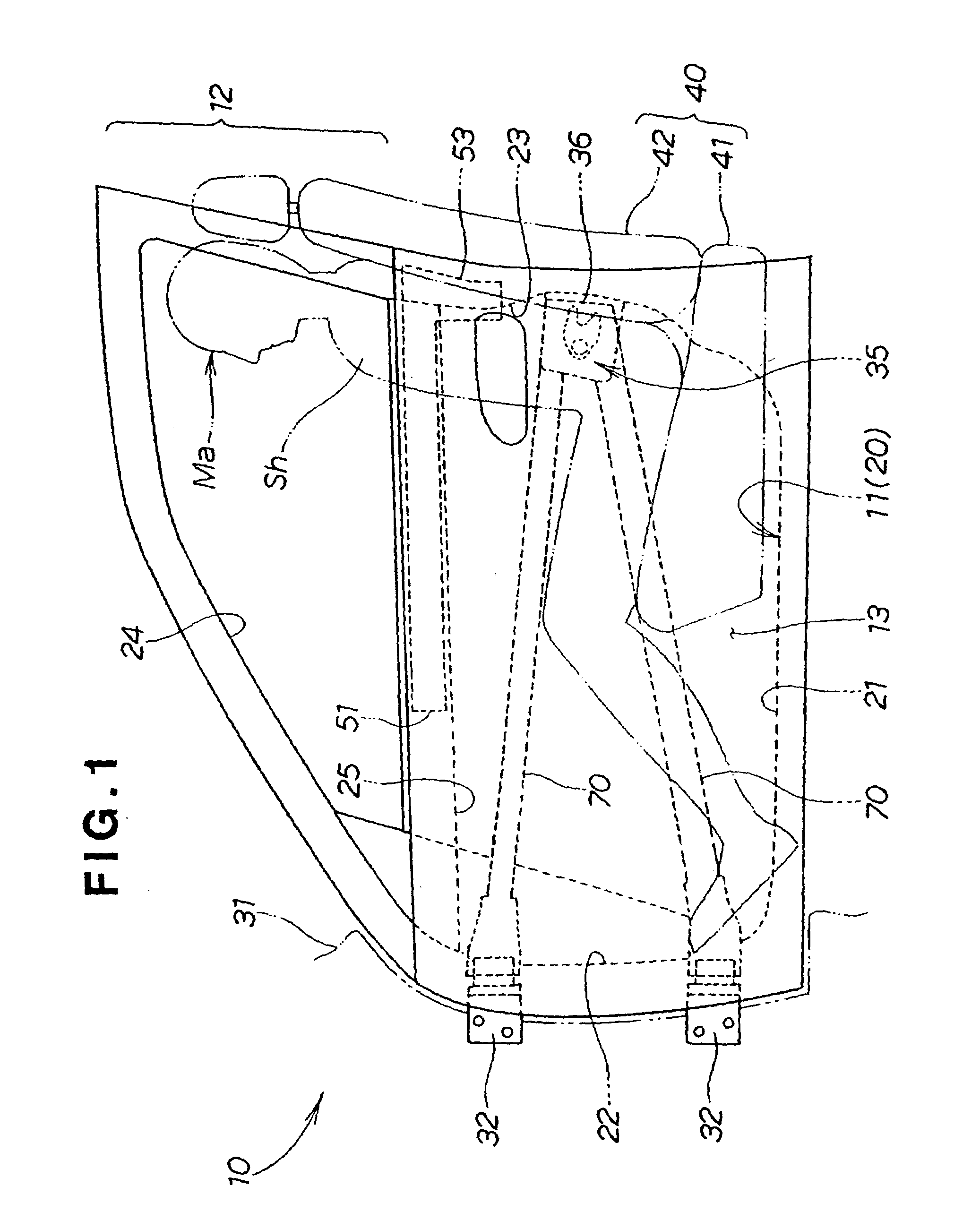
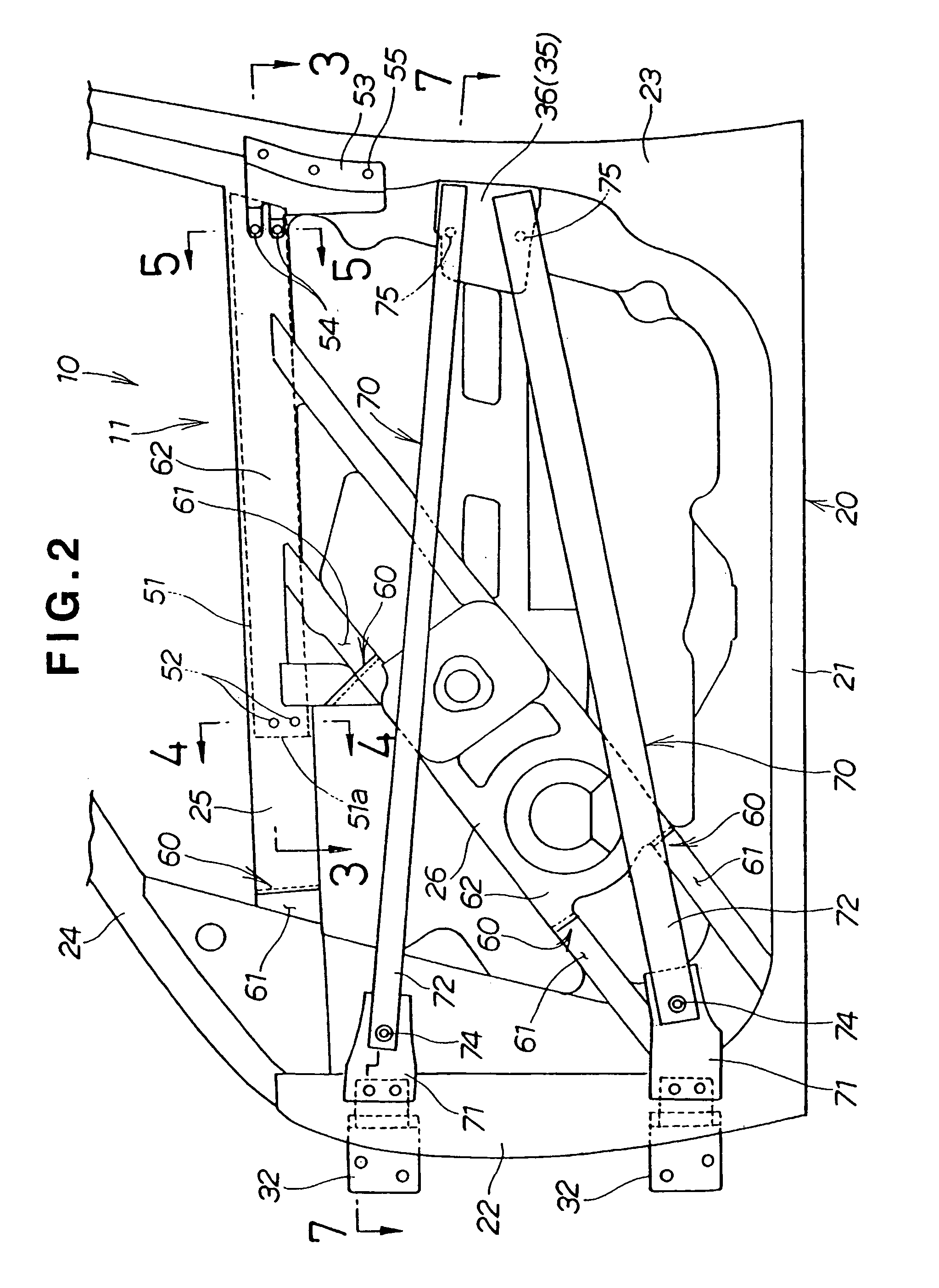
[0019]FIG. 1 shows a structure of a left front door 10 of a full-door type vehicle as viewed from a left side of the door 10. The door 10 is composed of an inner door panel 11 having a window sash 12 formed integrally with an upper end portion thereof, and an outer door panel 13 joined with an outer side—i.e., a side facing a viewer of the figure—of the inner door panel 11. The door 10 is mounted for opening and closing movement with a door frame 20 of the inner door panel 11 attached via upper and lower hinges 32 to a vehicle body 31 denoted by a phantom line in the figure, and it is held in the closed position by means of a door lock section 35 secured to the door frame 20.

[0020]The window sash 12 is a component holding therein a door glass (not shown) in such a manner that the glass can be raised and lowered along the sash 12. In this description, the terms “inner door panel” collectively refer to a combination of the panel 11 and window sash 12.

[0021]The door frame 20 of the inn...


PUM


Abstract

A vehicle door (10) includes a door frame (20), hinges (32) for attaching the door frame to a vehicle body (31) therethrough in such a manner that the door frame moves between open and closed positions, a door lock section (35) for holding the vehicle door in a closed position, and door beams (70) connected between the hinges and the door lock section. Each door beam includes a series a plural dividing members. The plural dividing members have their respective end portions (71b, 72a) overlapped with each other in a widthwise direction of the vehicle body and joined with each other in such a manner that the dividing members are movable relative to each other by a predetermined distance when a collision force acts on the doorbeam.

Description

TECHNICAL FIELD[0001]The present invention relates to a technique for improving performance of a door to protect a passenger or driver (hereinafter, generically referred to as a passenger) in a motor vehicle.BACKGROUND ART[0002]In recent years, techniques have been developed for protecting a passenger of a vehicle from a collision force acting on the vehicle. For enhanced passenger protecting performance, there has been a demand for reconsideration of the overall vehicle body structure including doors. As an example of a vehicle door designed to enhance the passenger protecting performance, there is known a “vehicle door structure” disclosed in Japanese Patent Laid-open Publication No. HEI-7-25236.[0003]The disclosed vehicle door has an inner door panel mounted via upper and lower hinges to a vehicle body to move between open and closed positions. The vehicle door has a door lock device for holding the door closed. The inner door panel includes an impact bar extending between the hi...

Claims


Application Information

Patent Timeline
Patent Type & Authority Patents(United States)
IPC IPC(8): B60J5/04E05D5/04E05D5/06E05D5/02E05D5/00B60R21/02B60J5/00
CPCB60J5/0431B60J5/0433B60J5/0437B60J5/0448E05D5/023E05D5/043E05D5/062E05Y2900/531
Inventor OMORI, TOSHIHISAKITAYAMA, KENICHI
Owner HONDA MOTOR CO LTD
Why Eureka
Try Eureka