

Plant lighting apparatus
- Summary
- Abstract
- Description
- Claims
- Application Information
AI Technical Summary
Benefits of technology
Problems solved by technology
Method used
Image

Examples
first embodiment
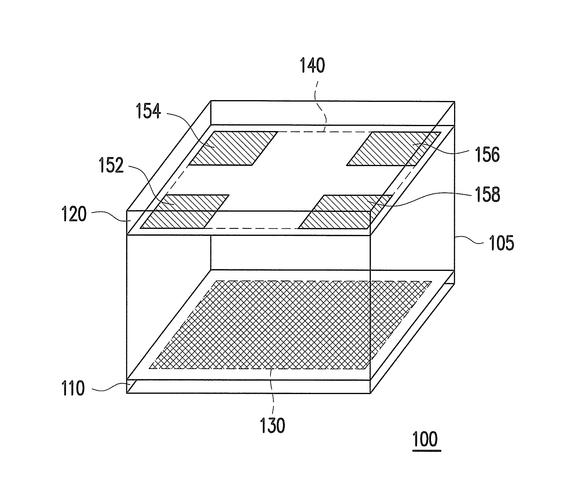
[0040]FIG. 1 is a block schematic diagram of a plant lighting apparatus 100 according to a first embodiment of the invention. Referring to FIG. 1, the plant lighting apparatus 100 includes a main body 105, a planting region 130, and an emitting region 140. In the present embodiment, the main body 105 can be a cubic box, which has a bottom plane (which is also referred to as a first plane) 110 and a top plane (which is also referred to as a second plane) 120. The first plane and the second plane are opposite to each other. For example, the first plane and the second plane are parallel to each other. The bottom plane (the first plane 110) and the top plane (the second plane) 120 have a certain space therebteween. In this way, plants growing in the planting region 130 may have a proper growing space, and can get sufficient lights. In an embodiment of the invention, the bottom plane (the first plane 110) and the top plane (the second plane) 120 are spaced by 200 mm. Moreover, besides th...
second embodiment
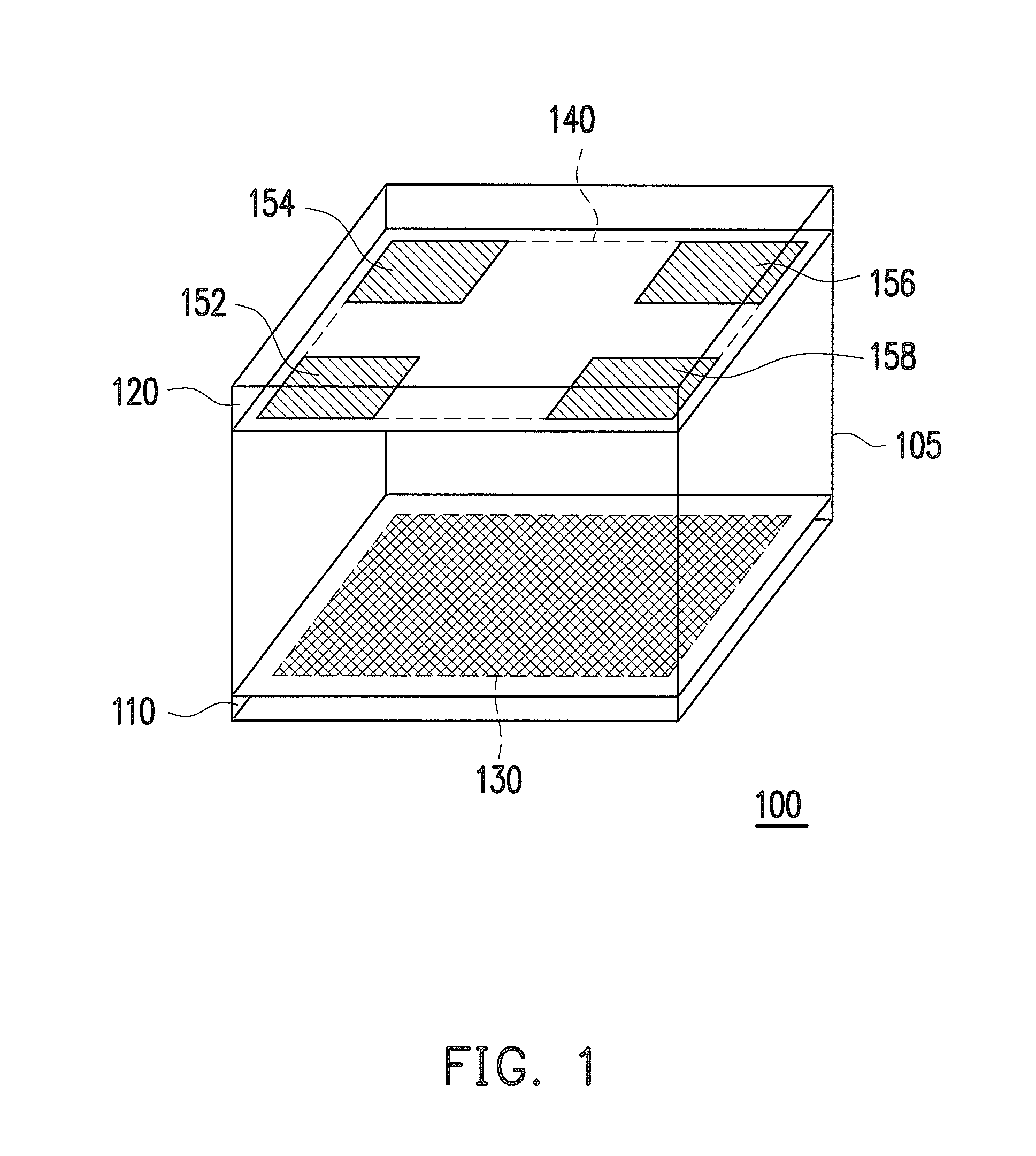
[0044]FIG. 2 is a block schematic diagram of a light source configuration of a plant lighting apparatus 200 according to a second embodiment of the invention. Referring to FIG. 2, for simplicity's sake, the main body, the bottom plane (the first plane), the planting region, etc. of the plant lighting apparatus 200 of FIG. 2 are omitted, and only a top plane (the second plane) 220 and an emitting region 240 of the plant lighting apparatus 200 are illustrated. In detail, in the present embodiment, the emitting region 240 is, for example, a rectangle and includes two long sides and two short sides. Particularly, in order ensure that the light sources on the emitting region 240 to uniformly irradiate the planting region, besides a plurality of sets of the main light sources are configured, at least one set of secondary light sources is configured at other parts of the main body. The set of secondary light sources is used for compensating insufficient light irradiation of the main light ...
third embodiment
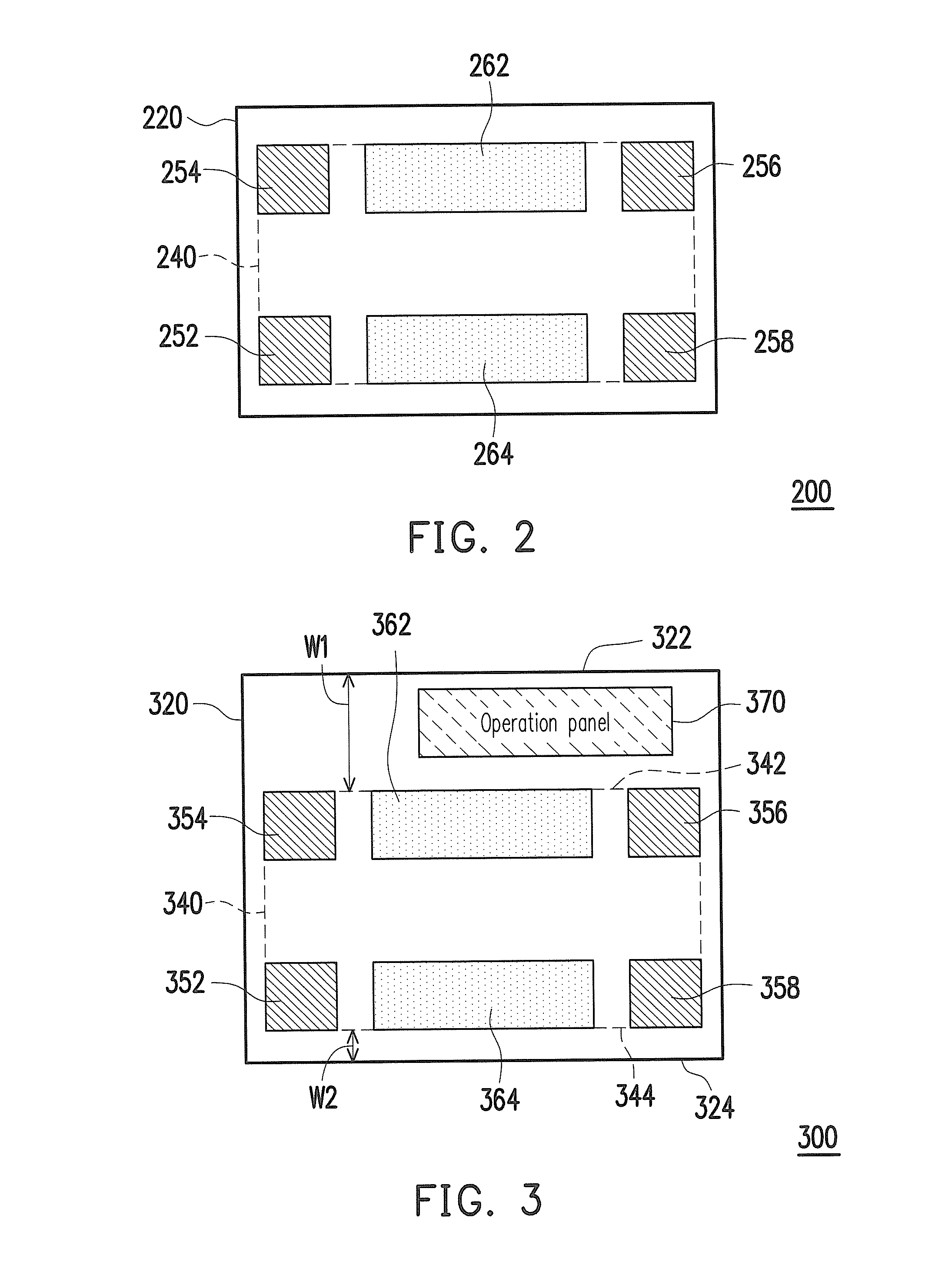
[0045]FIG. 3 is a block schematic diagram of a light source configuration of a plant lighting apparatus 200 according to a third embodiment of the invention. Referring to FIG. 3, for simplicity's sake, the main body, the bottom plane (the first plane), the planting region, etc. of the plant lighting apparatus 300 of FIG. 3 are omitted, and only a top plane (the second plane) 320 and an emitting region 340 of the plant lighting apparatus 300 are illustrated. In the present embodiment, the top plane (the second plane) 320 includes the emitting region 340 and an operation panel 370. The operation panel 370 is used for controlling the plant lighting apparatus 300, and may have a control circuit for controlling current supplying, or setting an illumination time, etc. of the plant lighting apparatus. The operation panel 370 can be disposed at one side of the man body, one side of the planting region or one side of the top plane (the second plane) 320, which is not limited by the invention...
PUM
 Abstract
Description
Claims
Application Information