
Apparatus and method for auto-pairing of remote controller using NFC tag

a remote controller and tag technology, applied in the field of remote controller technology, can solve the problems of inconvenient series of processes, and achieve the effect of simple tagging and simple calling of additional functions

Inactive Publication Date: 2016-07-07
PACHEM KOREA
View PDF5 Cites 23 Cited by
  • Summary
  • Abstract
  • Description
  • Claims
  • Application Information

AI Technical Summary

Benefits of technology

The present invention is about a method to pair electronic devices using a Radio Frequency (RF) method. The invention allows for easy tagging of electric appliances with a remote controller, and even allows for the removal and re-establishment of existing pairs without insisting on the use of a different electric appliance. Additionally, the invention makes use of RF communication to enable simple calling of additional functions using the paired electric appliance.

Problems solved by technology

When pairing needs to be frequently performed, for example, when pairing is alternately performed on different electric appliances, it is inevitably very inconvenient to perform a series of these processes.

Method used


Image

  • Apparatus and method for auto-pairing of remote controller using NFC tag
  • Apparatus and method for auto-pairing of remote controller using NFC tag
  • Apparatus and method for auto-pairing of remote controller using NFC tag

Examples


example 2

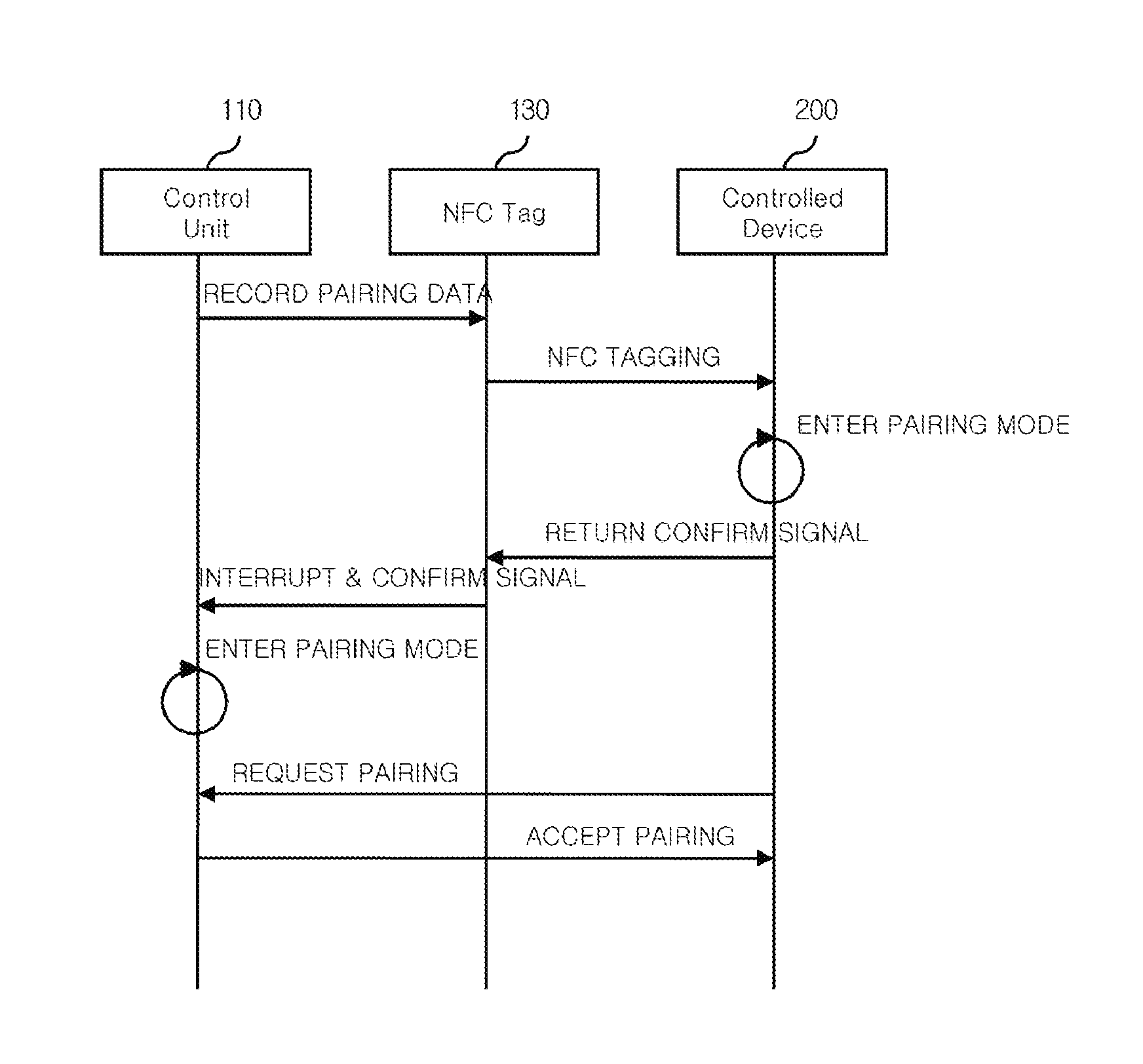
[0128]Hereinafter, one aspect of a method for auto-pairing of a remote controller using an NFC tag according to an embodiment of the present invention will be described in detail with reference to FIG. 5.

[0129]FIG. 5 is a flowchart illustrating a method for auto-pairing of a remote controller using an NFC tag in terms of a remote controller 100 according to an embodiment of the present invention.

[0130]That is, the present invention shown in FIG. 5 may be executed in the remote controller 100.

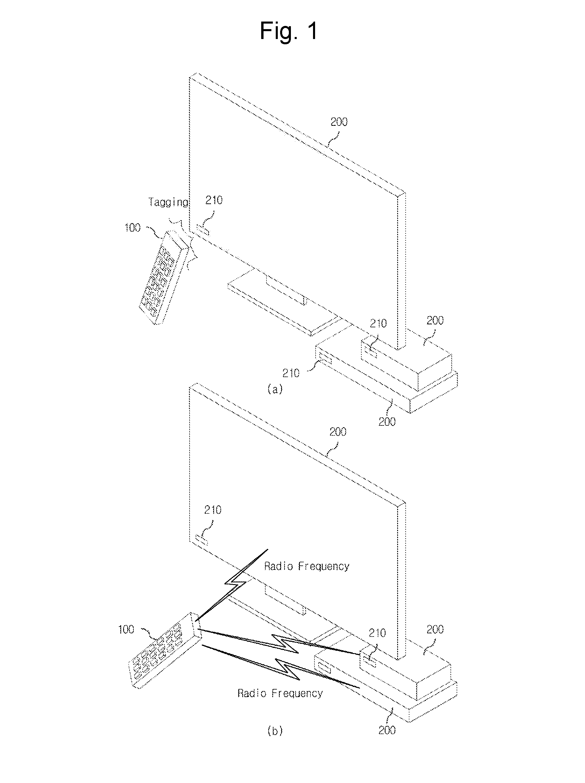
[0131]When a user brings the remote controller 100 into contact or close proximity to the NFC receiver 210 and thus tagging occurs between the NFC tag 130 and the NFC receiver 210, pairing data may be transmitted from the NFC tag 130 to the NFC receiver 210 of the controlled device 200 (operation c-1).

[0132]On this other hand, as described in the above-mentioned embodiment, when the controlled device 200 enters the pairing mode through the processes according to the flag values, the remote contr...


PUM


Abstract

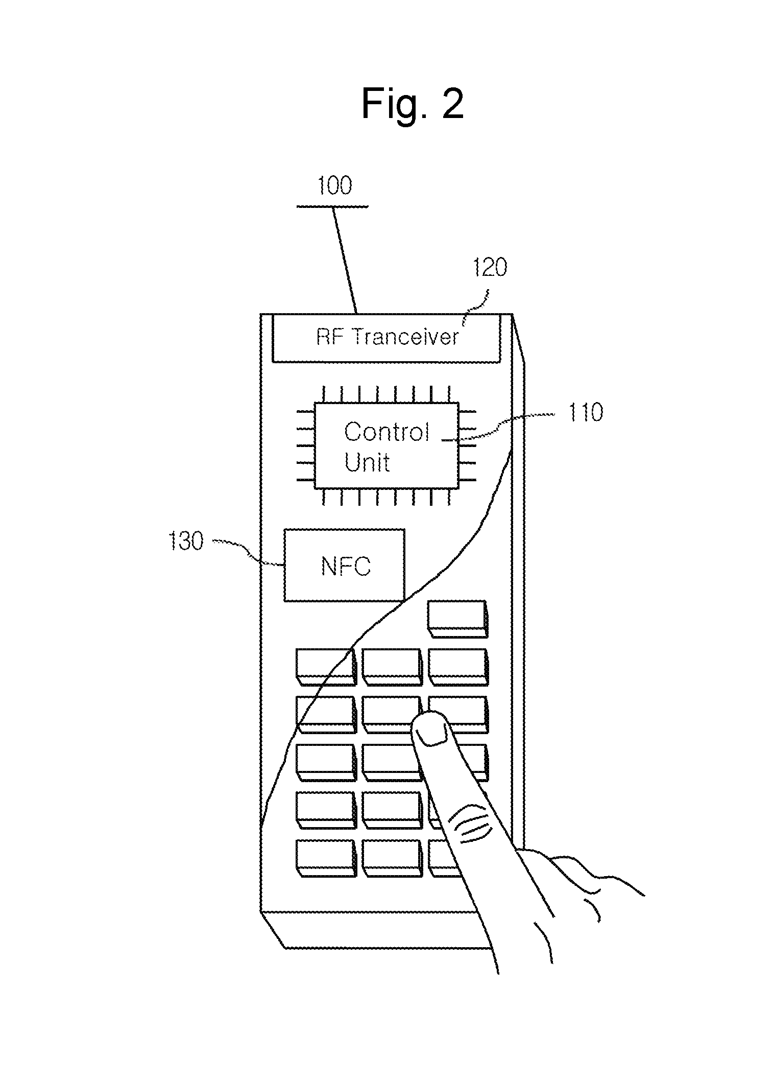
Provided are an apparatus and a method for auto-pairing of a remote controller using an NFC tag. In the NFC tag, a flag indicating whether to pair the NFC tag, identification information of the remote controller and security information are stored and transmitted to an NFC receiver of a controlled device upon tagging. The controlled device enters a pairing mode according to the value of the flag and the identification information of the remote controller and returns a confirmation signal. The remote controller, which receives the confirmation signal, also enters a pairing mode. In this state, the controlled device requests pairing from the remote controller in an RF communication manner, and pairing is established through an automatic authentication process.

Description

TECHNICAL FIELD[0001]The present invention disclosed herein relates to a remote controller technology field.BACKGROUND ART[0002]A remote controller is used to wirelessly manipulate various kinds of electric appliances.[0003]For communication between a remote controller and an electric appliance to be controlled, infra-red frequency and radio frequency and the like are being widely used. In spite of low cost, the infra-red is gradually disappearing due to short communication distance and reduction of the receiving rate by obstacles.[0004]Meanwhile, it is general that these remote controllers are released while frequencies and device coded for communication with electric appliances to be controlled are preset.[0005]However, when a remote controller is not set so as to be communicable with a specific electric appliance, a user needs to undergo a process of pairing the remote controller and the electric appliance in order to operate a desired electric appliance.[0006]In regard to a typi...

Claims


Application Information

Patent Timeline
Patent Type & Authority Applications(United States)
IPC IPC(8): G08C17/02H04W4/00H04B5/00H04W4/80
CPCG08C17/02H04B5/0031G08C2201/61G08C2201/20H04W4/008H04L63/18H04W12/06H04W4/80H04W12/47H04W12/50H04B5/77H04B5/20H04B5/70G06K17/0022H04Q9/02H04Q9/04H04Q2209/47H04B5/72
Inventor PARK, RHAE KWON
Owner PACHEM KOREA
Learn More