String winding and unwinding apparatus
a string and unwinding technology, applied in the direction of fasteners, press-button fasteners, footwear, etc., can solve the problems of cumbersome tightening or tightening, user inconvenience, loosening of strings, etc., to achieve convenient tightening and loosening of strings, loosening of shoelaces, and easy loosening
- Summary
- Abstract
- Description
- Claims
- Application Information
AI Technical Summary
Benefits of technology
Problems solved by technology
Method used
Image

Examples
second embodiment
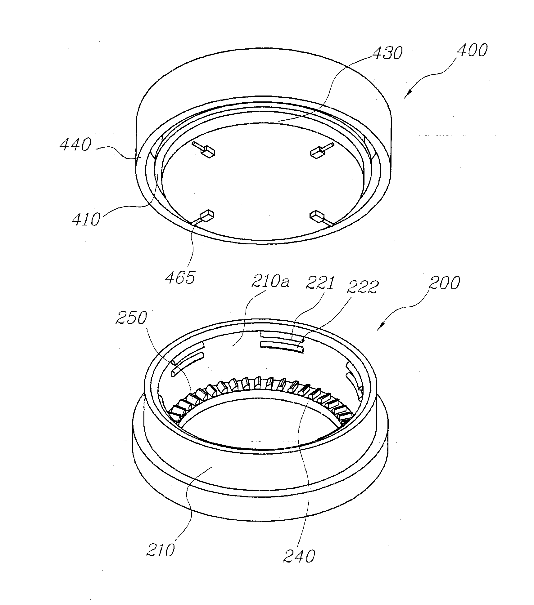
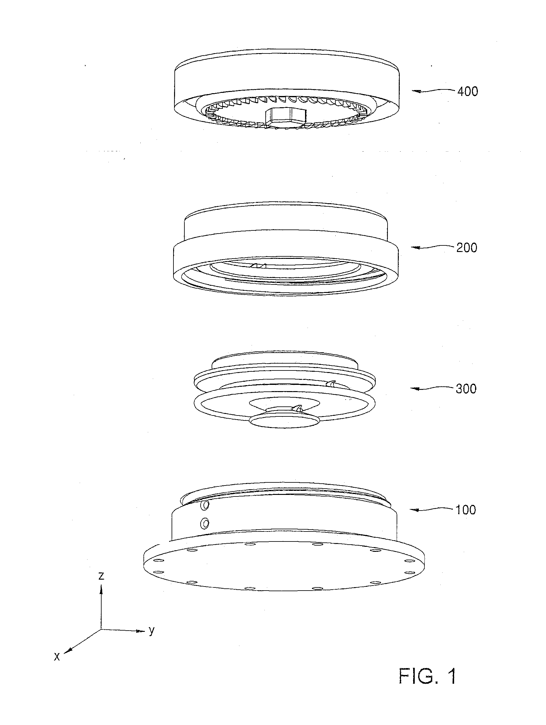
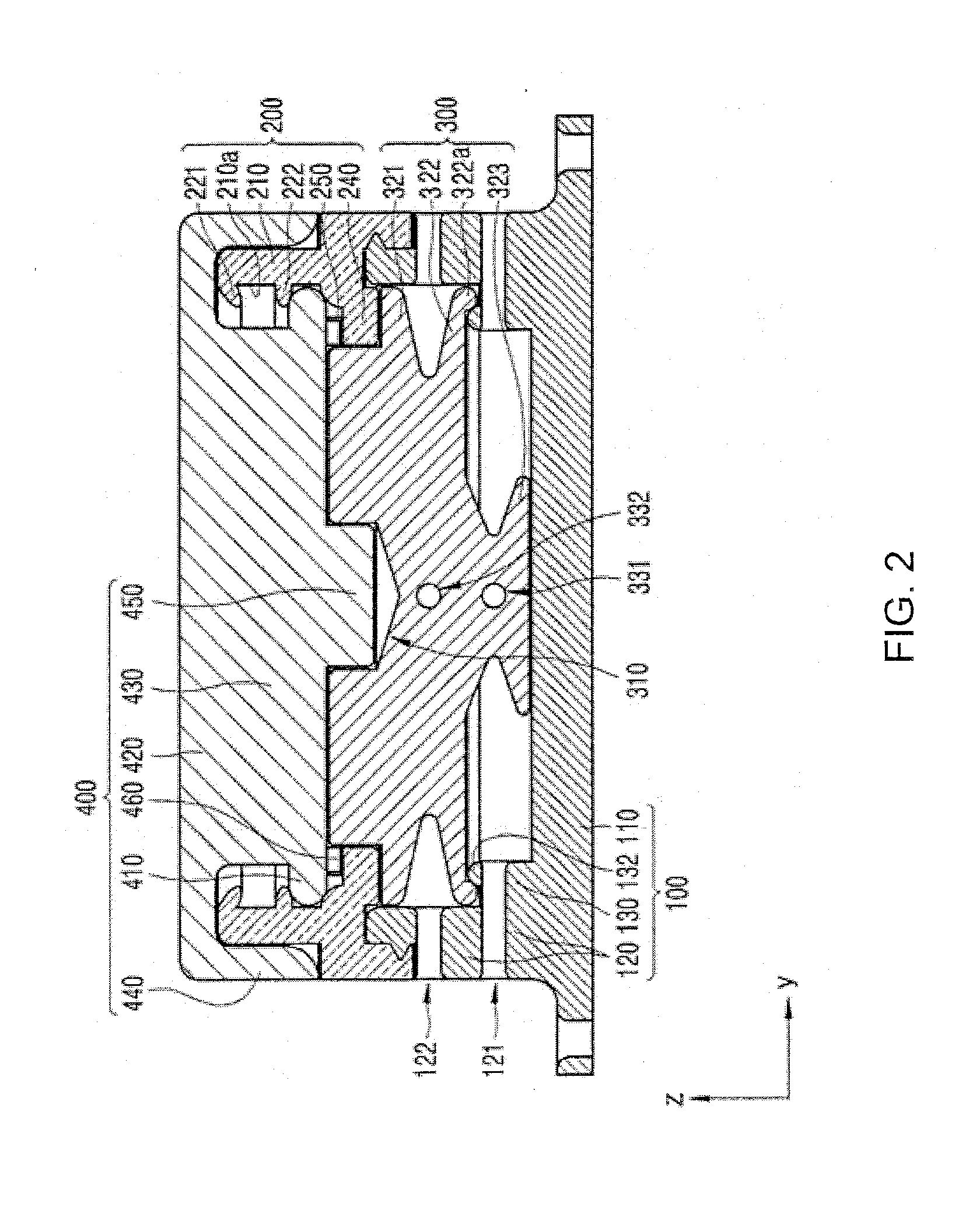
[0165]According to another embodiment (second embodiment having a 2-stage configuration) of the present disclosure illustrated in FIGS. 31 and 32, like the embodiment of FIGS. 28 through 30, the stoppage portion elements 410 and 270 and the reverse rotation preventing portion elements 460 and 250 between the cover unit 400 and the middle unit 200, and the engaging portion elements 450 and 310 between the cover unit 400 and the rotating unit 300 are all included in a first stage (I), and the string winding portion elements 321 and 322 of the rotating unit 300 are included in a second stage (II). As a result, the height of the apparatus may be lowered, relative to the 3-stage configuration of FIG. 27.
[0166]Hereinafter, the elements will be described in even further detail. First, in the reverse rotation preventing portion elements 460 and 250, the responsive protrusion 250 of the middle unit 200 is formed on the partition 240 (in the +z direction). Here, compared with the partition 24...
third embodiment
[0172]According to another embodiment (third embodiment having a 2-stage configuration) of the present disclosure illustrated in FIGS. 33 and 34, like the embodiment of FIGS. 28 through 30, the stoppage portion elements 410 and 270 and the reverse rotation preventing portion elements 460 and 250 between the cover unit 400 and the middle unit 200, and the engaging portion elements 450 and 310 between the cover unit 400 and the rotating unit 300 are all included in a first stage (I), and the string winding portion elements 321 and 322 of the rotating unit 300 are included in a second stage (II). As a result, the height of the apparatus may be lowered, relative to the 3-stage configuration of FIG. 27.
[0173]Compared with the embodiments described above, the present embodiment has the following differences. First, among the stoppage portion elements 470 and 215, the elastic stoppage portion 470 is formed in the cover unit 400, rather than in the middle unit 200, and the responsive protru...
fourth embodiment
[0180]According to another embodiment (fourth embodiment having a 2-stage configuration) of the present disclosure illustrated in FIGS. 35 and 36, like the embodiment of FIGS. 28 through 30, the stoppage portion elements 410 and 270 and the reverse rotation preventing portion elements 460 and 250 between the cover unit 400 and the middle unit 200, and the engaging portion elements 450 and 310 between the cover unit 400 and the rotating unit 300 are all included in a first stage (I), and the string winding portion elements 321 and 322 of the rotating unit 300 are included in a second stage (II). As a result, the height of the apparatus may be lowered, relative to the 3-stage configuration of FIG. 27.
[0181]In the present embodiment, like the embodiment of FIG. 33 described above, among the stoppage portion elements 470 and 215, the elastic stoppage portion 470 is formed in the cover unit 400, rather than in the middle unit 200, and the responsive protrusion portion 215 is formed in th...
PUM
 Abstract
Description
Claims
Application Information
 - R&D
- Intellectual Property
- Life Sciences
- Materials
- Tech Scout
- Unparalleled Data Quality
- Higher Quality Content
- 60% Fewer Hallucinations
Browse by: Latest US Patents, China's latest patents, Technical Efficacy Thesaurus, Application Domain, Technology Topic, Popular Technical Reports.
© 2025 PatSnap. All rights reserved.Legal|Privacy policy|Modern Slavery Act Transparency Statement|Sitemap|About US| Contact US: help@patsnap.com