Mechanical part die with die releasing conveniently conducted

A technology of mechanical parts and molds, which is applied in the field of mechanical molds, can solve problems such as single structure, low work efficiency, and low production efficiency, and achieve the effects of improving work efficiency, improving demoulding efficiency, and reducing work difficulty

Inactive Publication Date: 2018-12-18
任大龙
View PDF0 Cites 12 Cited by
  • Summary
  • Abstract
  • Description
  • Claims
  • Application Information

AI Technical Summary

Problems solved by technology

[0003] However, there are still some deficiencies in the existing molds for mechanical parts. On the one hand, the structure is single, and the connection between the forming blank and the inner and outer walls of the mold is relatively tight, which makes the demoulding work time-consuming and laborious, and the work efficiency is not high. On the other hand, After the blank is cast, the cooling and forming speed is relatively slow, resulting in low production efficiency

Method used


Image

  • Mechanical part die with die releasing conveniently conducted
  • Mechanical part die with die releasing conveniently conducted
  • Mechanical part die with die releasing conveniently conducted

Examples


Embodiment 1

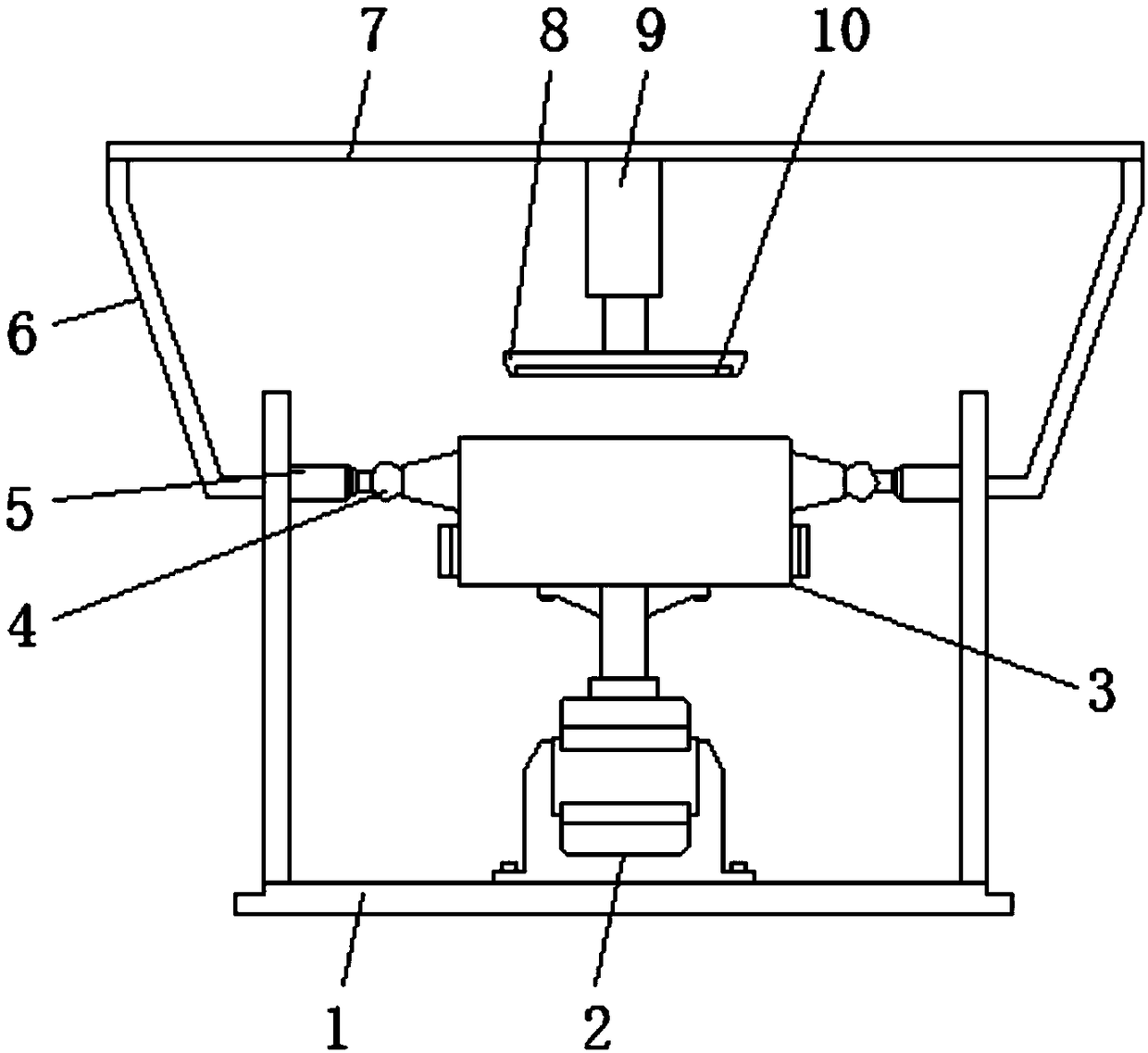
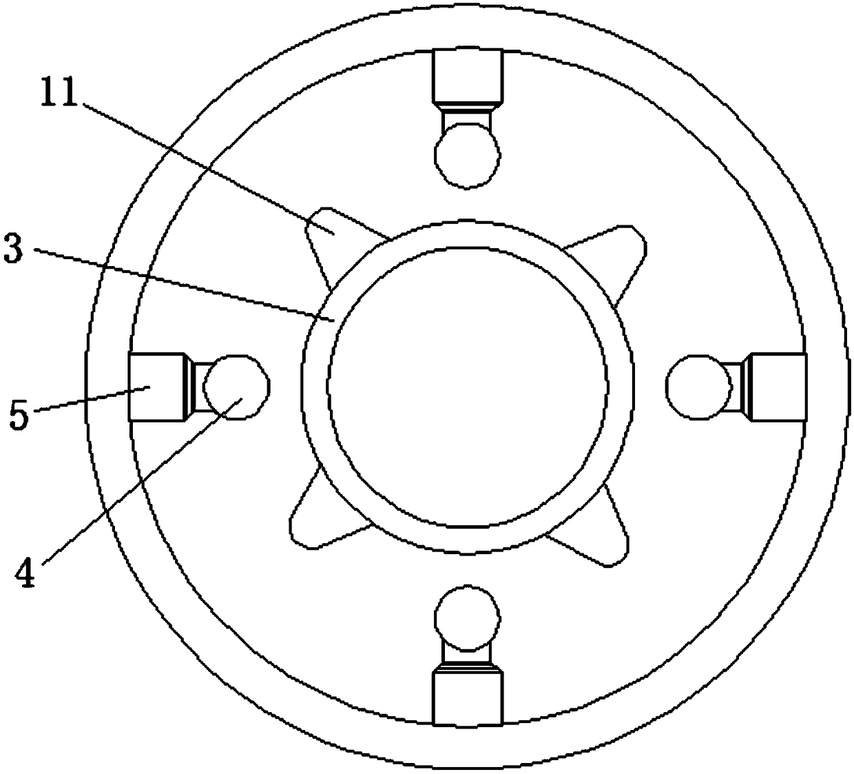
[0025] Embodiment one, with reference to Figure 1-2 , a mold for mechanical parts that is easy to demould, including an outer cylinder body 1 and a mold body 3, a drive motor 2 is fixedly connected to the top center of the inner surface wall at the bottom of the outer cylinder body 1, and the top of the drive motor 2 passes through the output shaft The transmission is connected with a mold body 3, and the outer side of the mold body 3 is welded with a plurality of arc angle bumps 11 equiangularly around its center, and the outer sides of the plurality of arc angle bumps 11 are welded equiangularly on the inner surface wall of the outer cylinder body 1 There are a plurality of telescopic rods 5, steel balls 4 are welded to the ends of the plurality of telescopic rods 5 near the mold body 3, and the plurality of telescopic rods 5 and the plurality of arc angle bumps 11 are located on the same horizontal straight line, driven by The motor 2 drives the mold body 3 to rotate, so t...

Embodiment 2

[0026] Embodiment two, refer to Figure 4 , a plurality of telescopic rods 5 are combined by return spring 51, sleeve 52, 5 slider 53 and pole 54, the inside of sleeve 5 is slidingly sleeved with slider 53, and one side of slider 53 passes through the return spring 51 is elastically connected to the inner surface wall of one side of the sleeve 52, and a strut 54 is welded on the other side. When the arc angle protrusion 11 contacts the steel ball 4, the strut 54 pushes the slider 53 to slide in the sleeve 5, The return spring 51 is compressed under force, thereby avoiding the deviation of the steel ball 4 under force and ensuring its position stability.

Embodiment 3

[0027] Embodiment three, refer to figure 1 , the top of the outer wall on both sides of the outer cylinder body 1 is welded to the top plate 7 through the symmetrically arranged fixing frame arms 6, and the center of the bottom of the top plate 7 is connected to the fixed plate 8 through the MYT3-23 hydraulic pusher 9, and the bottom of the fixed plate 8 The electromagnetic plate 10 is fixedly connected. When the blank and the inner wall of the mold body 3 become loose, the electromagnetic plate 10 is controlled to descend by the MYT3-23 hydraulic pusher 9 and contacts the upper surface of the blank. After the electromagnetic plate 10 is energized, a strong magnetic field is generated. Thereby, the blank can be absorbed and recovered by the MYT3-23 hydraulic pusher 9, and the blank can be easily taken out.


PUM


Abstract

The invention discloses a mechanical part die with die releasing conveniently conducted. The mechanical part die comprises an outer cylinder body and a die body. A drive motor is fixedly connected tothe center position of the top of the inner surface wall of the bottom of the outer cylinder body, and the top of the drive motor is in drive connection with the die body through an output shaft. Multiple arc angle protruding blocks are welded to the outer side of the die body at equal angles around the circle center of the die body. According to the mechanical part die, the arc angle protruding blocks are arranged on the outer side of the die body, steel balls are arranged on the inner surface wall of the outer cylinder body, the drive motor is used for driving the die body to rotate so thatthe arc angle protruding blocks can collide with the steel balls intermittently, a knocking vibration effect is generated, and a blank part can be loosened from the die body through the knocking vibration effect. In addition, a certain centrifuging effect can be generated in the rotating process of the die body, and the blank part can be more easily loosened from the die body through the centrifugal force. Furthermore, due to the arrangement of an MYT3-23 hydraulic thruster and an electromagnetic plate, the blank part can be easily taken out, the working difficulty is lowered, and the die releasing efficiency is improved.

Description

technical field [0001] The invention relates to the technical field of mechanical molds, in particular to a mold for mechanical parts that is easy to demould. Background technique [0002] Mold machinery is a tool used to shape objects. This tool is composed of various parts. Different molds are composed of different parts. It mainly realizes the processing of the shape of the object through the change of the physical state of the formed material. Stamping, die forging, cold heading, extrusion, powder metallurgy parts pressing, pressure casting, and compression molding or injection molding of engineering plastics, rubber, ceramics and other products, used to make the blank into a specific shape under the action of external force and dimensions of the workpiece tool. [0003] However, there are still some deficiencies in the existing molds for mechanical parts. On the one hand, the structure is single, and the connection between the forming blank and the inner and outer wall...

Claims


Application Information

Patent Timeline
Patent Type & Authority Applications(China)
IPC IPC(8): B22D29/04B22D29/06B22D30/00
CPCB22D29/04B22D29/06B22D30/00
Inventor 任大龙
Owner 任大龙
Why Eureka
Try Eureka