Safety gate

a safety gate and gate body technology, applied in the field of safety gates, can solve the problems of inconvenience in use, the difficulty of only one person to independently mount the conventional safety gate, etc., and achieve the effect of convenient mounting, convenient and convenient loosing

Active Publication Date: 2013-04-16
WANG TSUNG HSIANG
View PDF10 Cites 17 Cited by
  • Summary
  • Abstract
  • Description
  • Claims
  • Application Information

AI Technical Summary

Benefits of technology

[0016]The shaft fixing assembly serves to fix a relative distance between the first frame and the second frame. The stretcher assembly and the second shaft rack are used to further stretch out the first frame and the second frame so that the safety gate tightly abuts against two walls of a mounting premise and does not topple. When the safety gate is not in use, the safety gate can be loosened easily from the walls after the stretcher assembly is released and the safety gate can be then moved to elsewhere for storing. Without the readjustment of the shaft fixing assembly, the same relative distance between the first frame and the second frame can be repeatedly applied to subsequent mountings. Accordingly, the safety gate can be mounted easily and conveniently.

Problems solved by technology

A successful mounting of the conventional safety gate relies on simultaneous and tight contact of the edges of the movable frames with the door frame and the locking of the fixing element at the same time to prevent the safety gate from easily toppling and falling, but it is rather difficult for only one person to independently mount the conventional safety gate.
However, the fixing elements and the stretcher elements of the conventional safety gates are designed and manufactured in combination, or in other words, they can only be operated at the same time.
Such readjustment over and over again causes inconvenience in use and the conventional safety gates need to be further improved.

Method used


Image

  • Safety gate
  • Safety gate
  • Safety gate

Examples


Embodiment Construction

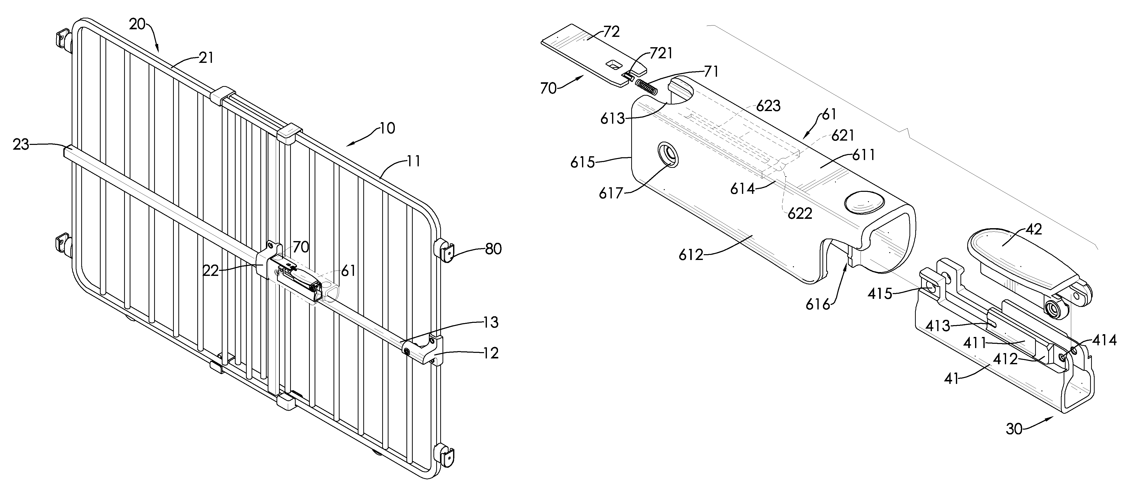
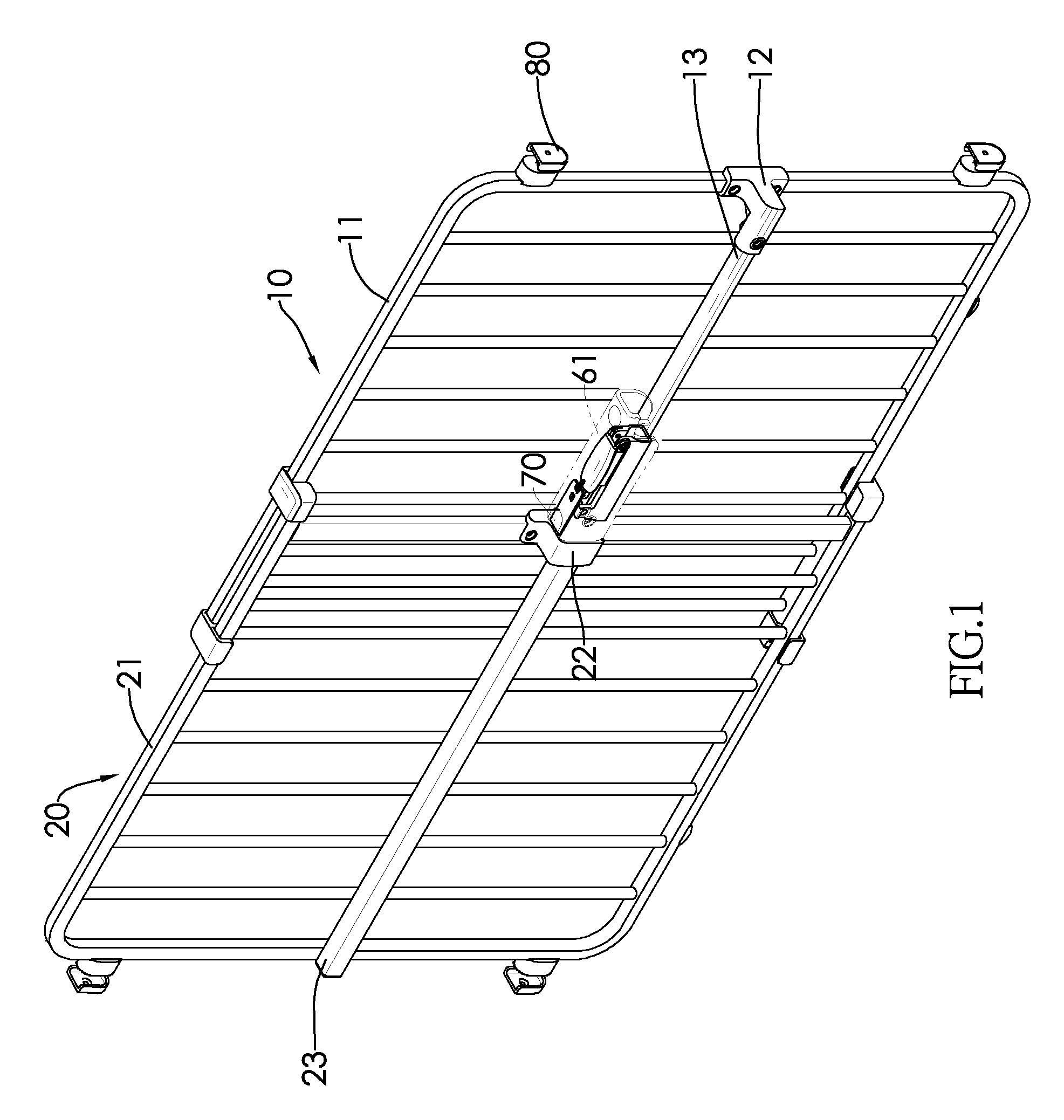
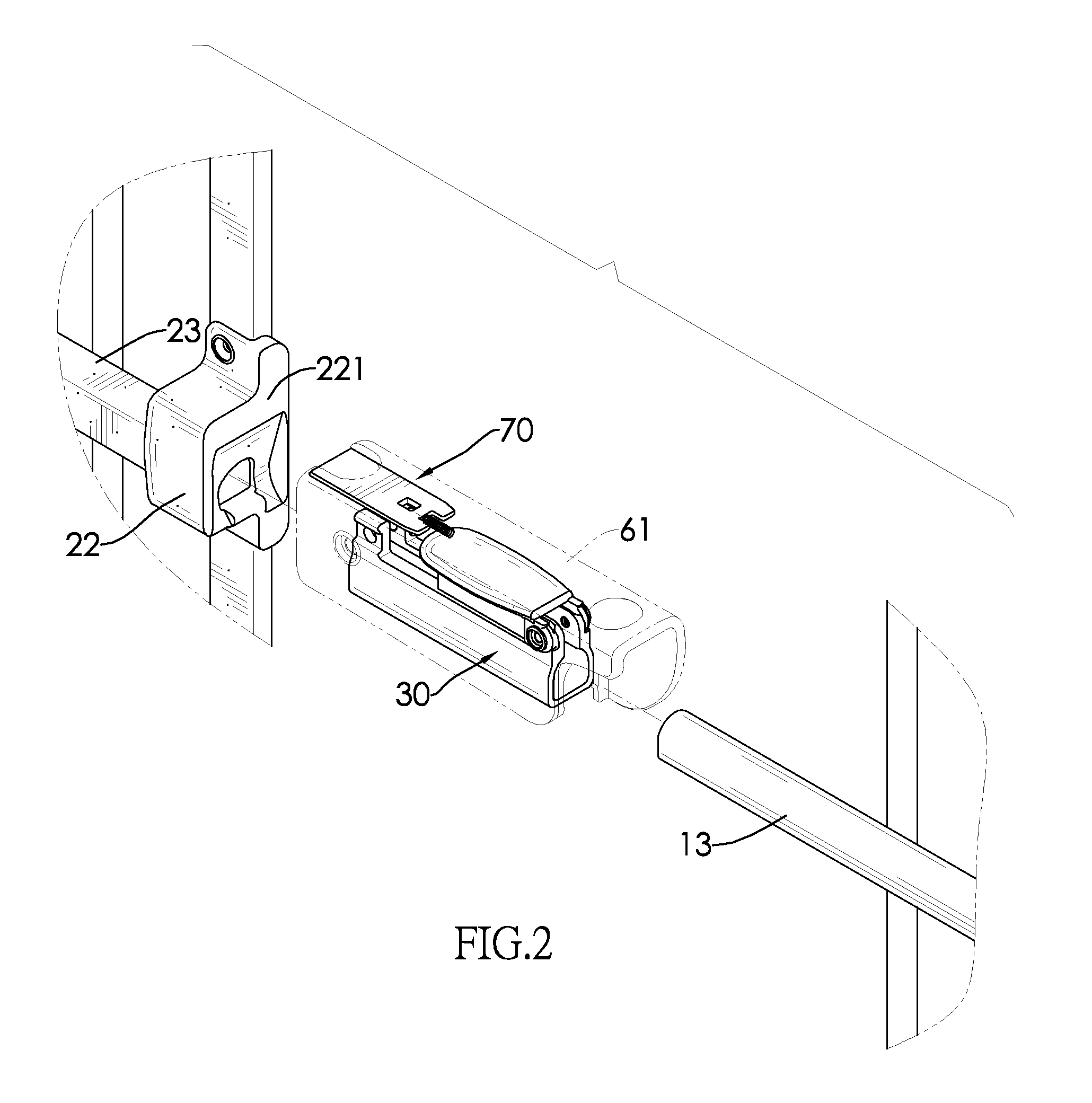
[0027]With reference to FIGS. 1 and 2, a safety gate in accordance with the present invention has a first frame assembly 10, a second frame assembly 20, a shaft fixing assembly 40, a stretcher assembly 61, an anti-pinch assembly 70 and multiple contact pads 80.

[0028]With reference to FIGS. 1 to 5, the first frame assembly 10 has a first frame 11, a first shaft rack 12 and a first shaft 13. The first shaft rack 12 is mounted on one side edge of the first frame 11 in a transverse direction. The first shaft 13 is securely mounted on the first shaft rack 12 and has a non-circular section.

[0029]The second frame assembly 20 is adjacent to the other side edge of the first frame 11 in the transverse direction and has a second frame 21, a second shaft rack 22 and a second shaft 23. The second frame 21 is mounted between the first frame 11 and the first shaft 13. A slider is mounted on each of the top edges and the bottom edges of the first frame 11 and second frame 21 so that the first frame...


PUM


Abstract

A safety gate has two frame assemblies, a shaft fixing assembly and a stretcher assembly. A relative distance between the two frame assemblies is fixed by the shaft fixing assembly first. The stretcher assembly further pushes the two frame assemblies outwardly so that the two frame assemblies tightly abut against two walls of a mounting premise and can be held on the walls securely. When the safety gate is not in use, the stretcher assembly is released to loosen the safety gate from the walls and the stretcher assembly can be moved to elsewhere. As the safety gate can be repeatedly mounted without having to readjust the relative distance between the two frame assemblies with the shaft fixing assembly, the operation of the safety gate is easy and convenient.

Description

BACKGROUND OF THE INVENTION[0001]1. Field of the Invention[0002]The present invention relates to a safety gate, and more particularly to a safety gate capable of locking a distance between two sides of the safety gate for the purpose of repeated mountings.[0003]2. Description of the Related Art[0004]Safety gates serve to block young children or pets at the top of stairs for a fall protection or at the entrance to a room, such as kitchen or living room, to limit the infants or pets to stay in the room or from accessing the room.[0005]A conventional safety gate substantially comprises two movable frames and a fixing element. After the two movable frames are adjusted to abut against two opposite sides of an entrance, the fixing element is used to keep the movable frames at the relative distance so that the safety gate can be tightly mounted on the sides of the entrance in completion of the mounting process.[0006]A successful mounting of the conventional safety gate relies on simultaneo...

Claims


Application Information

Patent Timeline
Patent Type & Authority Patents(United States)
IPC IPC(8): E05C21/02E06B9/01E06B3/68E06B7/00
CPCE06B9/0623E06B9/0676E06B2009/002
Inventor WANG, TSUNG-HSIANG
Owner WANG TSUNG HSIANG
Why Eureka
Try Eureka