Large current connector

a current connector and large technology, applied in the direction of coupling base/case, coupling device connection, incorrect coupling prevention, etc., can solve the problems of inability to save assembly time, coupling cannot be achieved, male plug and female socket cannot be securely fastened, etc., to prevent loosening and short circuit caused by deformation, and the effect of fast latching

Inactive Publication Date: 2007-05-08
HSIEH YU CHU
View PDF3 Cites 12 Cited by
  • Summary
  • Abstract
  • Description
  • Claims
  • Application Information

AI Technical Summary

Benefits of technology

[0004]Therefore the primary object of the present invention is to provide a large current connector to solve the problem of the conventional male plug and the female socket that easily loosen due to impact of external forces. The invention provides a male plug and a female socket that can be latched together quickly, and an insulation member to anchor metals plates wedged in the male plug and the female socket to prevent loosening and short circuit caused by deformation.
[0005]To achieve the foregoing object, the large current connector of the invention includes a male plug and a female socket. The male plug has a shell, a coupling member, a first upper metal plate and a first lower metal plate. The female socket has a sleeve, an insulation member, a second upper metal plate and a second lower metal plate. The sleeve has latch cavities on two sides corresponding to elastic latch elements on two sides of the shell so that they can be coupled together easily.

Problems solved by technology

In practice, the screwing elements tend to loosen when subject to external forces.
Moreover, if screwing holes have a slight deviation on the tolerance, the male plug and the female socket cannot be fastened securely.
Not only saving time on assembly and coupling cannot be achieved, electric conductivity also could be affected.

Method used


Image

  • Large current connector
  • Large current connector
  • Large current connector

Examples


Embodiment Construction

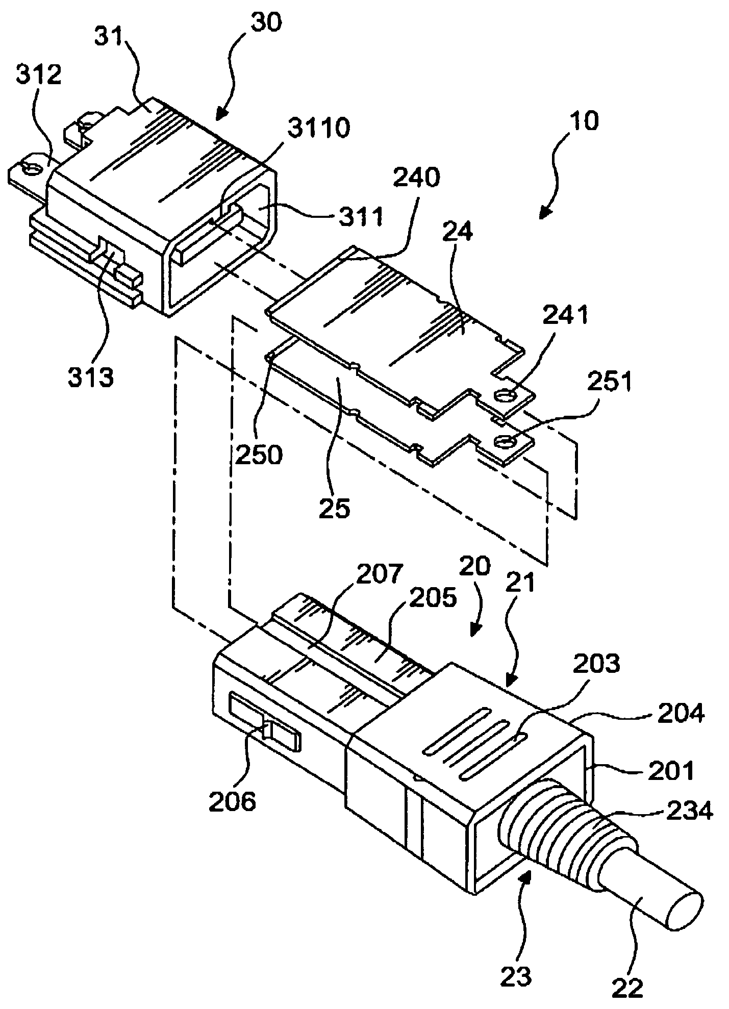
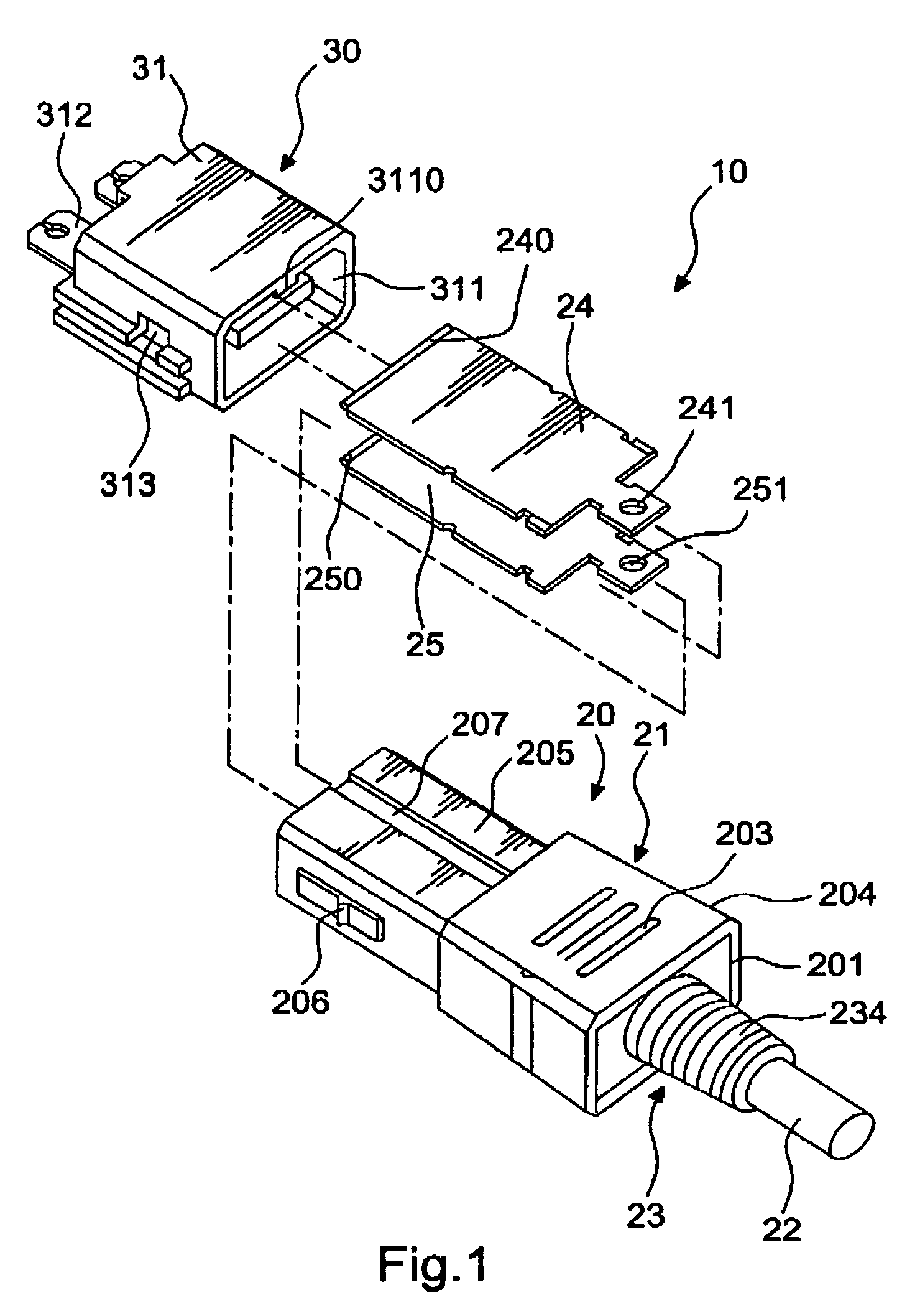
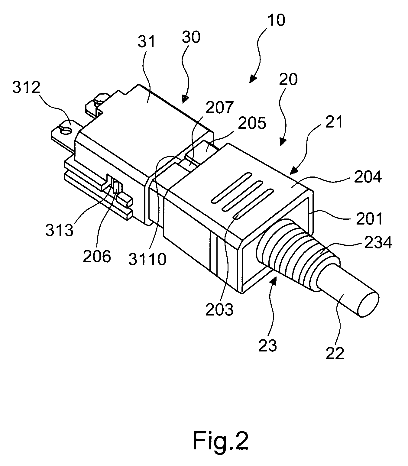
[0018]Please referring to FIGS. 1 and 3, the large current connector 10 according to the invention includes a male plug 20 and a female socket 30.

[0019]The male plug 20 includes a shell 21, a coupling member 23, a first upper metal plate 24 and a first lower metal plate 25. The shell 21 has two ends formed respectively a hollow body 201 and 202 that are interposed by latch troughs 2010. One end has a trapezoidal surface 204 with anti-slip transverse traces 203 (or ridges) formed thereon. Another end forms a coupling end 205 which has elastic latch elements 206 on two sides and a flute 207 on another side. The coupling member 23 has a latch end 231 on one end that mates the hollow body 201 of the shell 21 and has latch flutes 232 and 233 on a upper end and a lower end, and a first connection end 234 on another end to be run through by a core 22. The first upper and lower metal plates 24 and 25 run through the latch troughs 2010 and are wedged in the latch flutes 232 and 233, and have...


PUM


Abstract

A large current connector consists of a male plug and a female socket. The male plug includes a shell, a coupling member, a first upper metal plate and a first lower metal plate. The female socket includes a sleeve, an insulation member, a second upper metal plate and a second lower metal plate. The sleeve has latch cavities on two sides corresponding to and engageable with elastic latch elements on two sides of the shell. Thus the male plug and the female socket can be coupled together rapidly. The insulation member anchors the metal plates of the male plug and the female socket to prevent loosening thereof. Deformation of the metal plates also can be prevented to avoid short circuit.

Description

FIELD OF THE INVENTION[0001]The present invention relates to a large current connector and particularly to a connector which includes a male plug and a female socket that can be coupled together rapidly in a latch manner and an insulation member to anchor upper and lower metal plates wedged in the male plug and the female socket to prevent loosening and short circuit caused by deformation.BACKGROUND OF THE INVENTION[0002]Innovations of the peripherals and accessories of electric appliances progress constantly. Among them the connector elements consisting of a male plug and a female socket are widely used. They can be assembled and coupled together easily. However there are still room for improvement especially on enhancing the connectivity and simplifying assembly and coupling.[0003]Coupling of the male plug and the female socket of the conventional connector generally adopts screwing elements. In practice, the screwing elements tend to loosen when subject to external forces. Moreov...

Claims


Application Information

Patent Timeline
Patent Type & Authority Patents(United States)
IPC IPC(8): H01R13/627
CPCH01R13/53H01R13/6271H01R13/5845
Inventor HSIEH, YU-CHU
Owner HSIEH YU CHU
Why Eureka
Try Eureka