Needlefree valve device

a valve device and needle-free technology, applied in the direction of other medical devices, tube connectors, engine components, etc., can solve the problem of high manufacturing cos

Inactive Publication Date: 2016-07-14
CEDIC
View PDF58 Cites 3 Cited by
  • Summary
  • Abstract
  • Description
  • Claims
  • Application Information

AI Technical Summary

Benefits of technology

[0021]With further advantage, the second component comprises a guiding element enabling a guidance along the valve axis of the second component inside the first component. The guiding element allows for a smooth axial movement of the first and second component with respect to each other to ensure the closing and opening of the valve device. It should be noted that either component can comprise guiding elements, and that the guiding elements should enable a sufficient radial movement of the first and second component with respect to each other if the bayonet type locking mechanism is used.

Problems solved by technology

The structures of these connectors are complex, thus leading to high manufacturing costs.

Method used


Image

  • Needlefree valve device
  • Needlefree valve device
  • Needlefree valve device

Examples


first embodiment

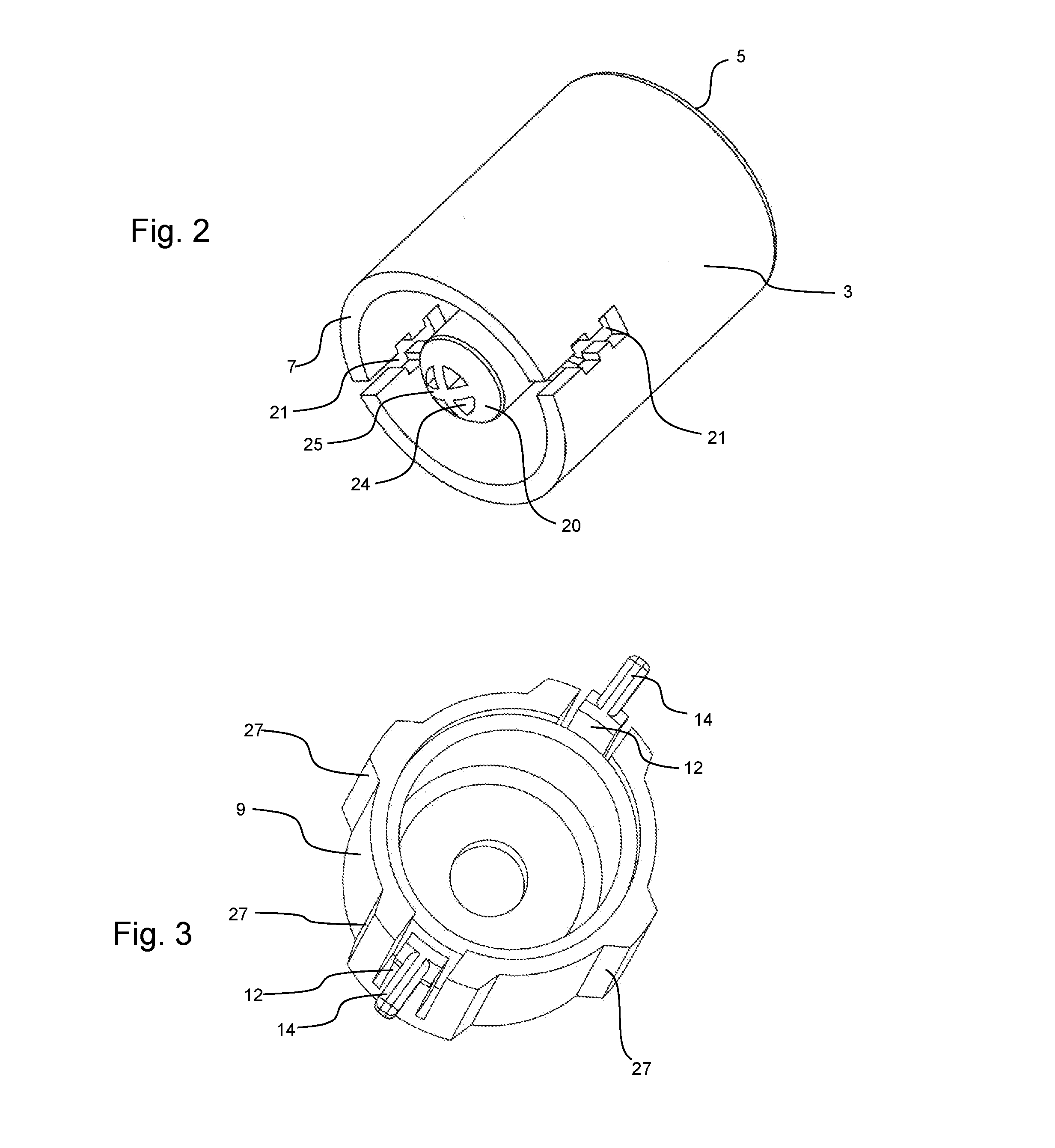
[0044]FIG. 2 is a detailed view of the first component of the valve device shown in FIG. 1. Beyond what was described with respect to FIG. 1, the male protrusion within the inside of sleeve-like first component 3 is clearly visible having a hemispherical contact surface 20 with four divider elements 25 and four flow channels 24 which enable fluid flow in the open configuration of the valve device. It should be noted that the shape of the male protrusion with convex contact surface 20 can be different from hemispherical. It may assume a planar, flat shape or a different curved shape. The main criterion for the shape of the protrusion and its contact surface is that it matches the inner surface of the first resilient portion 19 of sealing component 15 and its slit configuration as will be explained in greater detail below. In addition, a sufficient fluid flow through the flow channels 24 must be achieved. It should also be noted that the number of flow channels 24 and corresponding di...

second embodiment

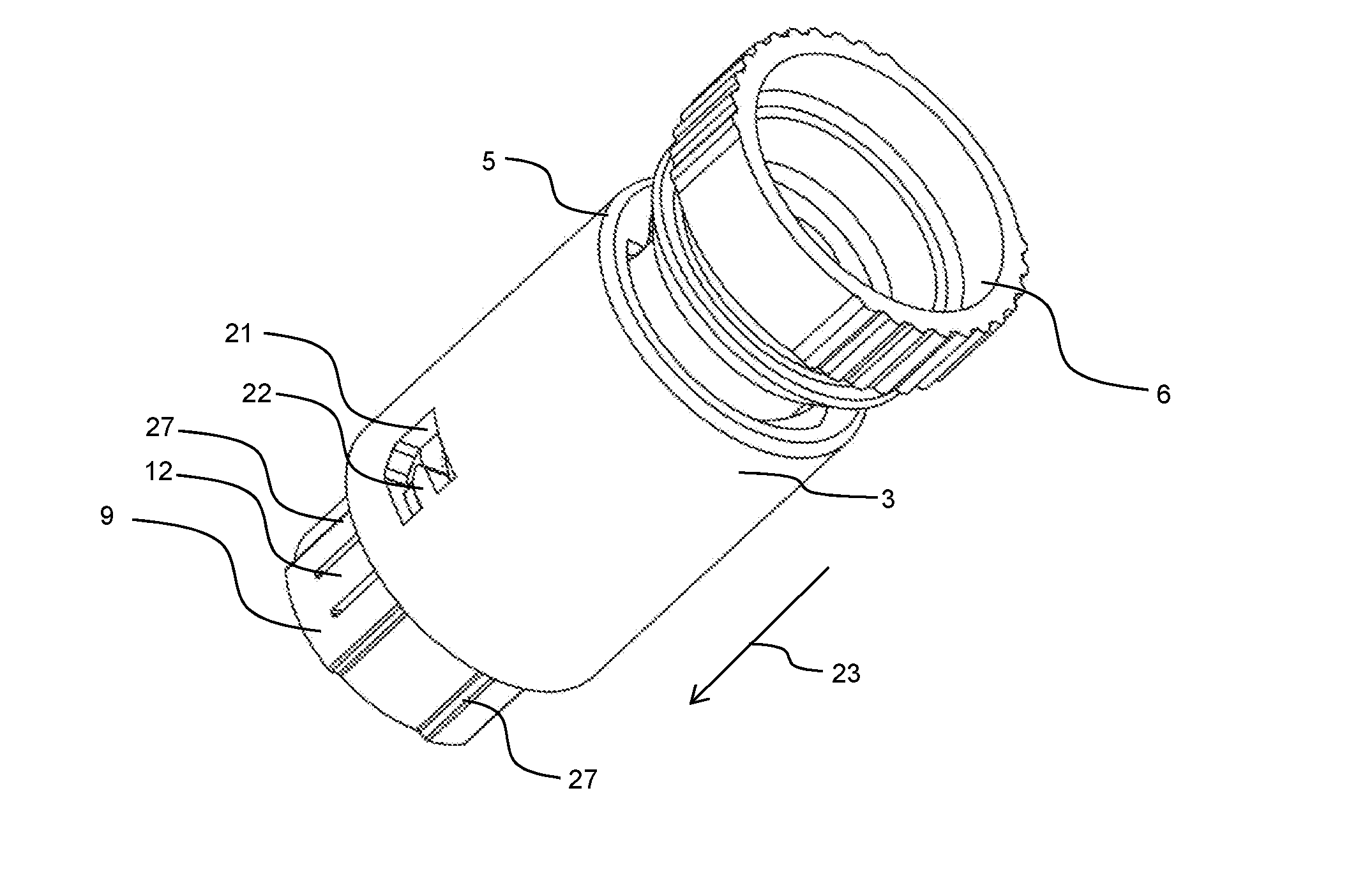
[0054]Recess 21 of first component 3 comprises a substantially rectangular or C-shaped configuration with a larger extension in the circumferential direction than in the axial direction parallel to the opening axis 23. Approximately in the middle of the longitudinal extension of recess 21 there is a locking arm 22 extending in a circumferential direction into recess 21 giving recess 21 a C-shape. In the embodiment shown as the second embodiment in FIGS. 7 to 17 the locking arm 22 extends from the right side wall in the outer surface of first component 3. The reason for this arrangement of locking arm 22 within recess 21 will become clear with respect to the detailed description of FIGS. 14 to 17 below.

[0055]The difference between the first and the second embodiment with respect to the locking mechanism is that in the second embodiment of FIG. 7 the free end of latch 12 near the valve end 13 does not comprise a grip protrusion 14 as in the first embodiment. This means that in the sec...


PUM


Abstract

Needlefree valve device (1) for controlling the flow of fluid in a pathway, the device (1) being operable in a closed and in an open configuration and comprising a first component (3), a second component (9), a locking means configured to selectively engage the first component (3) with the second component (9) in the open configuration when the first component (3) is displaced in an opening direction (23) along a valve axis toward the second component (9) or in the closed configuration when the first component (3) is displaced against the opening direction (23) away from the second component (9), and a sealing component (15) having a first resilient portion (19) and a second resilient portion (16), the first resilient portion (19) comprising at least one slit (26) and contacting the first component (9) to provide a seal in the closed configuration, wherein the first resilient portion (19) is adapted to move, buckle or flex to enable fluid flow through the at least one slit (26) upon application of a mechanical force of the first component (3) on the first resilient portion (19) in the opening direction (23) to assume the open configuration, and wherein the second resilient portion (16) is adapted to apply a counterforce to return the valve device (1) to the closed configuration when the mechanical force is no longer applied.

Description

CROSS-REFERENCE TO RELATED APPLICATIONS[0001]The present application is a U.S. national phase entry of pending International Patent Application No. PCT / EP2013 / 070279, international filing date Sep. 27, 2013, which claims priority to International Patent Application No. PCT / EP2013 / 067361, international filing date Aug. 21, 2013, the contents of which are incorporated by reference in their entireties.FIELD OF THE INVENTION[0002]The present invention generally relates to valve devices of the type used in the handling and administration of fluids, and more particularly to a needlefree medical valve device adapted to be used in any type of tube connection such as between the different kinds of ports and syringes, catheters, pumps, or the like which are used in the administration of all kinds of fluids. Examples of such administration are intravenous, enteral or parenteral delivery of fluids to or from a body.BACKGROUND OF THE INVENTION[0003]Needlefree valve connectors are known in the ar...

Claims


Application Information

Patent Timeline
Patent Type & Authority Applications(United States)
IPC IPC(8): A61M39/26A61M39/10
CPCA61M39/26A61M2039/1083A61M2039/1088A61M39/1011A61M39/045A61M39/22A61M2039/267
Inventor GAGLIARDONI, GIANCARLOMIJERS, JAN WILLEM MARINUS
Owner CEDIC
Why Eureka
Try Eureka