Eureka AIR delivers breakthrough ideas for toughest innovation challenges, trusted by R&D personnel around the world.

Turbine exhaust cylinder/ turbine exhaust manifold bolted stiffening ribs

Inactive Publication Date: 2016-07-14
SIEMENS ENERGY INC
View PDF1 Cites 1 Cited by
  • Summary
  • Abstract
  • Description
  • Claims
  • Application Information

AI Technical Summary

Benefits of technology

This patent describes a way to make components stiffer in a gas turbine, by using a casing arrangement with a damping blanket and stiffening ribs. The damping blanket reduces vibrations and keeps the inner flow path in contact with it, while the stiffening ribs provide additional strength to the components. Overall, this helps to make the gas turbine more efficient and reliable.

Problems solved by technology

The exhaust flow around the struts causes vibrations of the inner and outer diameter of the turbine exhaust cylinder and the turbine exhaust manifold due to vortex shedding.
These vibrations are a potential contributor to damage occurring to the flow path of the turbine exhaust manifold and the turbine exhaust cylinder.
This damage to the casing components may require early replacement or repair.

Method used


Image

  • Turbine exhaust cylinder/ turbine exhaust manifold bolted stiffening ribs
  • Turbine exhaust cylinder/ turbine exhaust manifold bolted stiffening ribs
  • Turbine exhaust cylinder/ turbine exhaust manifold bolted stiffening ribs

Examples


Embodiment Construction

[0017]To facilitate an understanding of embodiments, principles, and features of the present disclosure, they are explained hereinafter with reference to implementation in illustrative embodiments. Embodiments of the present disclosure, however, are not limited to use in the described systems or methods.

[0018]The components and materials described hereinafter as making up the various embodiments are intended to be illustrative and not restrictive. Many suitable components and materials that would perform the same or a similar function as the materials described herein are intended to be embraced within the scope of embodiments of the present disclosure.

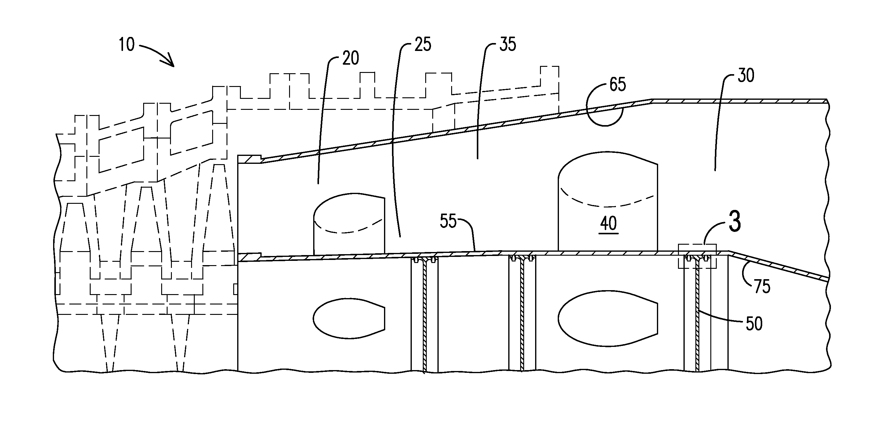
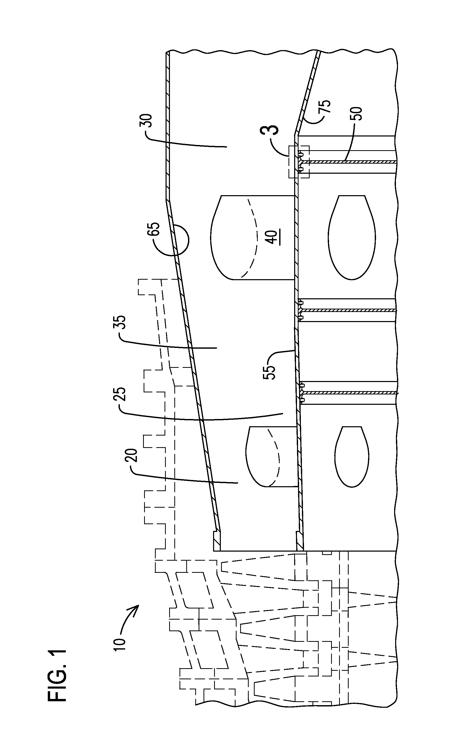
[0019]Damage to gas turbine casing components is an issue that may be caused by vibrations within the inner and outer flow path of the gas turbine exhaust system. The vibrations may be driven by insufficient component stiffness of the turbine exhaust cylinder and / or the turbine exhaust manifold. The stiffness of a component is defined...


PUM


Abstract

Disclosed are a casing arrangement and a method to reduce vibrations in a gas turbine casing. The casing arrangement includes a turbine exhaust cylinder connected to a turbine exhaust manifold establishing a fluid flow path, the fluid flow path including an inner and an outer flow path. A damping blanket damps the vibrations and is coupled to a surface of the inner flow path via a constraining layer.

Description

BACKGROUND[0001]1. Field[0002]The present application relates to gas turbines, and more particularly to a casing arrangement to improve component stiffness in a gas turbine, a casing arrangement to reduce operative vibrations, as well as a method to reduce critical panel mode response in a gas turbine casing and a method to reduce operative vibrations in a gas turbine casing.[0003]2. Description of the Related Art[0004]The turbine exhaust cylinder and the turbine exhaust manifold are coaxial gas turbine casing components connected together establishing a fluid flow path for the gas turbine exhaust. The fluid flow path includes an inner flow path and an outer flow path defined by an inner diameter delimiting an outer surface of the inner flow path and an outer diameter delimiting an inner surface of the outer flow path, respectively. Struts are arranged within the fluid flow path and serve several purposes such as supporting the inner and outer surfaces of the flow path and providing...

Claims


Application Information

Patent Timeline
IPC IPC(8): F01D25/04F01D25/24
CPCF01D25/04F05D2230/60F05D2220/32F01D25/24F01D25/162F01D25/30F05D2230/644
Inventor SHTEYMAN, YEVGENIY P.GIAIMO, JOHNESHAK, DANIEL M.HEYLMUN, THOMAS
Owner SIEMENS ENERGY INC
Why Eureka
Eureka Blog
Learn More