Steering bogie, and vehicle for track-based transportation system

a technology of track-based transportation and steering bogie, which is applied in the direction of rail derailment prevention, railway components, underframes, etc., can solve the problems of increasing costs, difficult application of steering bogies to large-sized vehicles, and limited vehicle weight, so as to achieve sufficient load bearing performance and reduce costs

Active Publication Date: 2016-07-21
MITSUBISHI HEAVY IND ENG LTD
View PDF2 Cites 15 Cited by
  • Summary
  • Abstract
  • Description
  • Claims
  • Application Information

AI Technical Summary

Benefits of technology

[0039]In the above steering bogie and the above vehicle for the track-based transportation system, the plurality of tires is mounted on an end section of each axle hub, so that sufficient load bearing performance can be obtained while holding down costs.

Problems solved by technology

For this reason, the weight of the vehicle is limited, and application of a steering carriage to a large-sized vehicle is difficult.
This becomes a factor of an increase in costs.
Additionally, in the single tire, the imposed load per tire becomes large.
Thus, there is also limitation to maximum speed, and the single tire is generally used in a speed zone of 80 km / h or less.

Method used


Image

  • Steering bogie, and vehicle for track-based transportation system
  • Steering bogie, and vehicle for track-based transportation system
  • Steering bogie, and vehicle for track-based transportation system

Examples


first embodiment

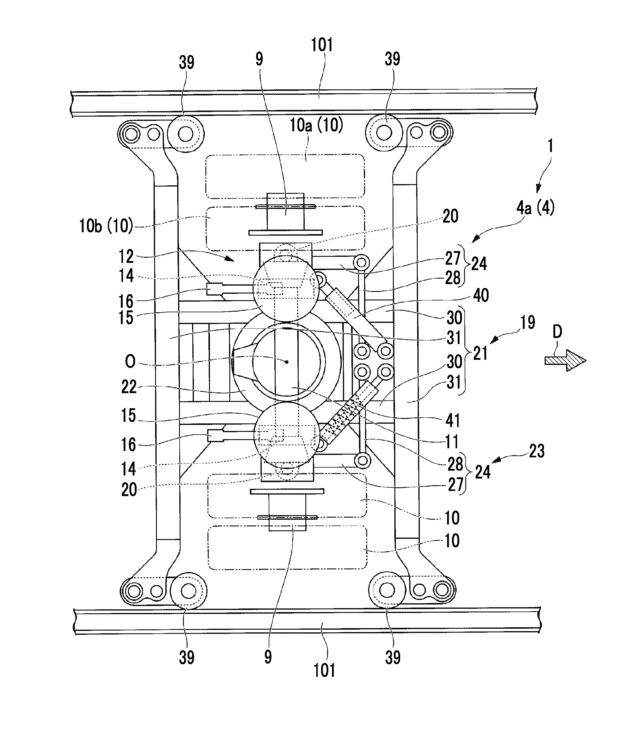
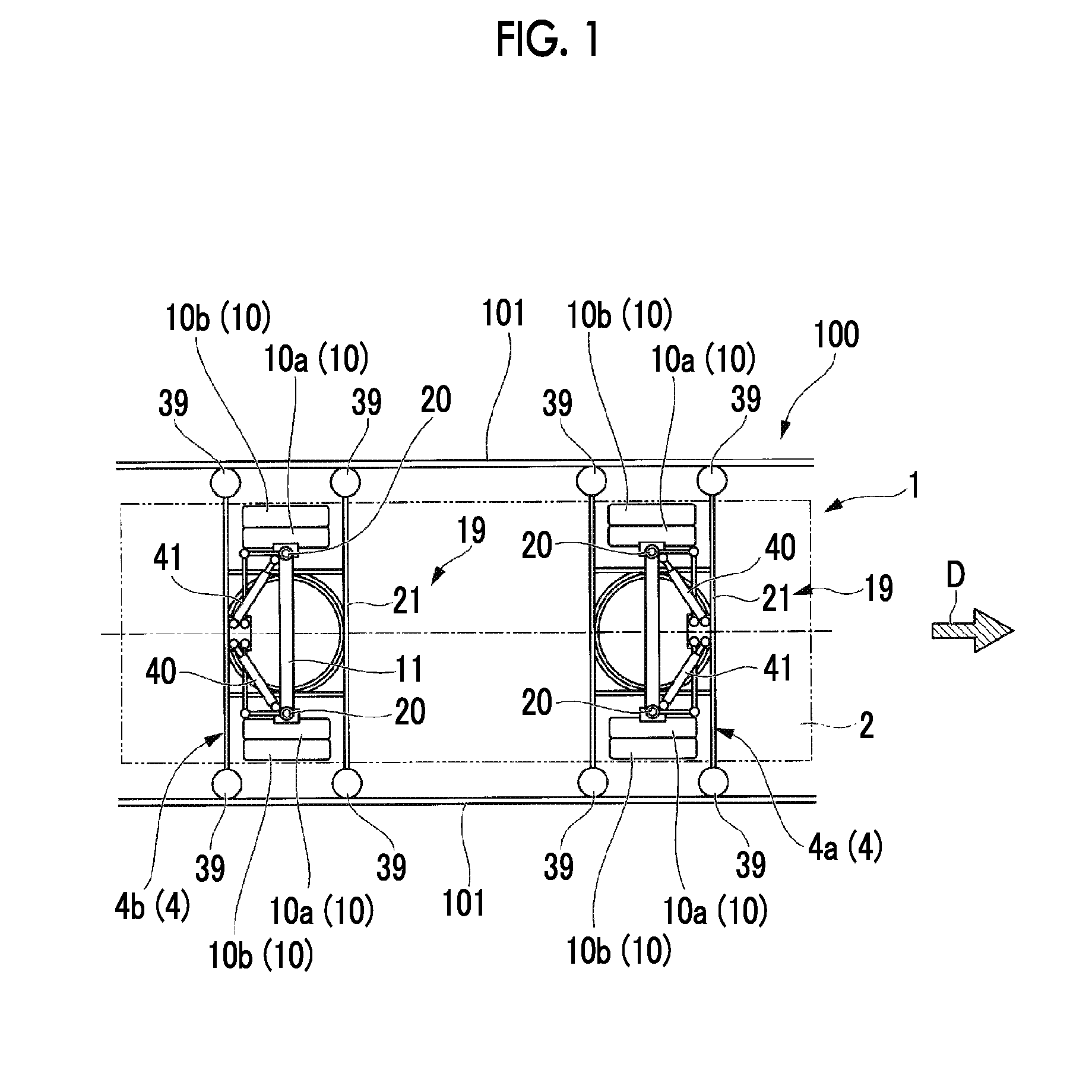
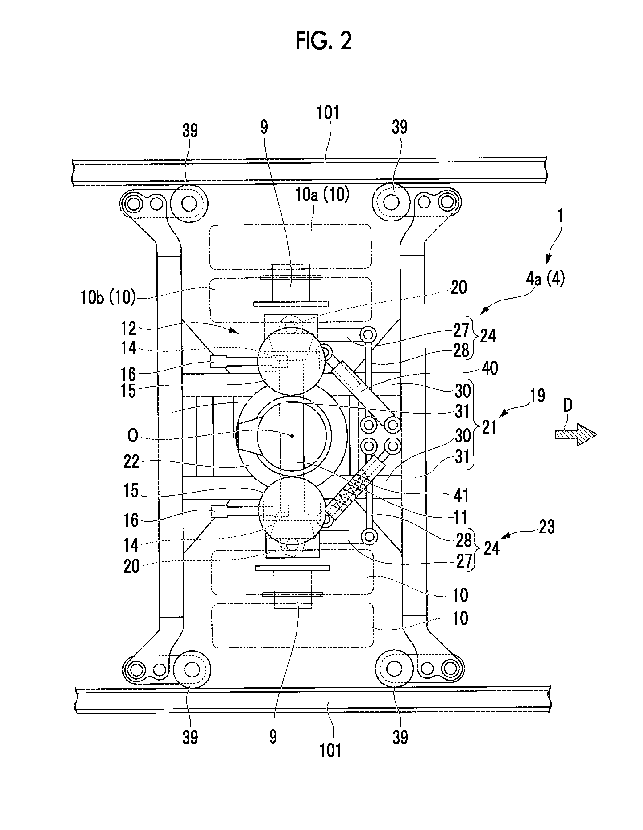
[0049]Hereinafter, a vehicle 1 related to a first embodiment of the invention will be described with reference to FIGS. 1 to 6.

[0050]As illustrated in FIG. 1, the vehicle 1 is a vehicle for a new transportation system that travels on a track 100 while being guided by a guide rail 101 provided at the track 100. In the present embodiment, the vehicle 1 is a vehicle for a side guide rail type (side guide type) transportation system in which guide rails 101 running along an extending direction of the track 100 are provided on both sides that come the outer sides of the track 100 in a width direction.

[0051]Additionally, the vehicle 1 includes a steering bogie 4 that travels or a traveling road surface 100a of the track 100, and a carbody 2 that is supported by the steering bogie 4.

[0052]The vehicle travels a direction (a rightward direction on the paper surface of FIG. 1) illustrated in arrow D of FIGS. 1, 2, 4, and 5. Hereinbelow, the front the rear facing in the traveling direction of ...

second embodiment

[0118]Hereinafter, a vehicle 1A related to a second embodiment of the invention will be described with reference to FIGS. 7 to 9.

[0119]As illustrated in FIGS. 7 to 9, a steering bogie 4A that the vehicle 1A of the present embodiment includes is different from the first embodiment in that the steering bogie is guided by one guide rail 101A provided at central position of the track 100 in the width direction.

[0120]That is, in the present embodiment, the vehicle 1A is a vehicle for a center guide rail type (center guide type) transportation system in which the guide rail 101A running along the extending direction of the track 100 is provided on the central position of the track 100 in the width direction.

[0121]Guide wheels in the steering bogie 4A are provided go as to sandwich one guide rail 101A provided on the track 100 from the width direction, at the central position in the width direction. The guide wheels 39, similar to the first embodiment, are provided in four places so as to ...


PUM


Abstract

This invention is equipped with: a steering shaft provided to an underframe of a carbody of a vehicle travelling on a traveling road surface of tracks; king pins provided as a pair to end sections of the steering shaft at both sides in the width direction; axle hubs swingably provided to the steering shaft via the king pins; tires mounted plurally to each of the axle hubs; guide wheels, which roll over guide rails provided to the tracks in the direction of extension of the tracks, and which are guided from the width direction of the tracks; a guide device part for supporting the guide wheels and the steering shaft; and a steering mechanism for causing the axle hubs to turn about the king pins in accordance with the displacement of the guide device part.

Description

TECHNICAL FIELD[0001]The invention present relates to a steering bogie of a track-based transportation system, and a vehicle including the steering bogie.[0002]Priority is claimed on Japanese Patent Application No. 2013-217737, filed Oct. 18, 2013, the content of which is incorporated herein by reference.BACKGROUND ART[0003]As new transportation means other than buses and railroads, track-based transportation systems in which a vehicle travels on a track using traveling wheels consisting of rubber tires, and guide wheels of the vehicle are guided by guide rails are known. Such track-based transportation systems are generally referred to as new transportation systems or automated people movers (APMs).[0004]In the track-based transportation systems, there are some systems in which tires of a steering bogie can be steered so as to be capable of smoothly passing through a curved portion of the track when traveling on the curved portion of the track. A tire to be steered is generally a s...

Claims


Application Information

Patent Timeline
Patent Type & Authority Applications(United States)
IPC IPC(8): B61F5/38B61B13/00B61F9/00
CPCB61F5/38B61B13/00B61F9/00
Inventor KATAHIRA, KOUSUKETAMURA, SOHOSHI, MITSUAKIMASUKAWA, MASAHISA
Owner MITSUBISHI HEAVY IND ENG LTD
Why Eureka
Try Eureka