Conveying device with an extensively extended conveying element

a conveying device and conveying element technology, applied in the field of conveying devices, can solve the problems of low power of drive units that are arranged within the conveying device, comparatively low construction height, and a particular challenge, and achieve the effect of low construction heigh

Active Publication Date: 2016-07-21
WRH WALTER REIST HLDG
View PDF2 Cites 1 Cited by
  • Summary
  • Abstract
  • Description
  • Claims
  • Application Information

AI Technical Summary

Benefits of technology

[0020]It is therefore the object of the invention, to suggest a conveying device of the initially mentioned type, which is designed in a compact manner and in particular has a low construction height.

Problems solved by technology

However, the comparatively low construction height represents a particular challenge, especially concerning the design and configuration of the drive device.
Although a drive device, which is arranged outside the conveying region, permits a reduced construction height of the conveying device for that region that forms the conveying surface, such a conveying device however is neither compact nor space-saving.
Thus drive units that are arranged within the conveying device are low in power due to their necessary compact design.
The construction length of such conveying devices is limited by way of this.
A modular construction of the conveying device, which is to permit large construction lengths can therefore hardly be implemented by way of conventional construction manners.

Method used


Image

  • Conveying device with an extensively extended conveying element
  • Conveying device with an extensively extended conveying element
  • Conveying device with an extensively extended conveying element

Examples


Embodiment Construction

[0128]Basically, the same parts are provided with the same reference numerals in the figures.

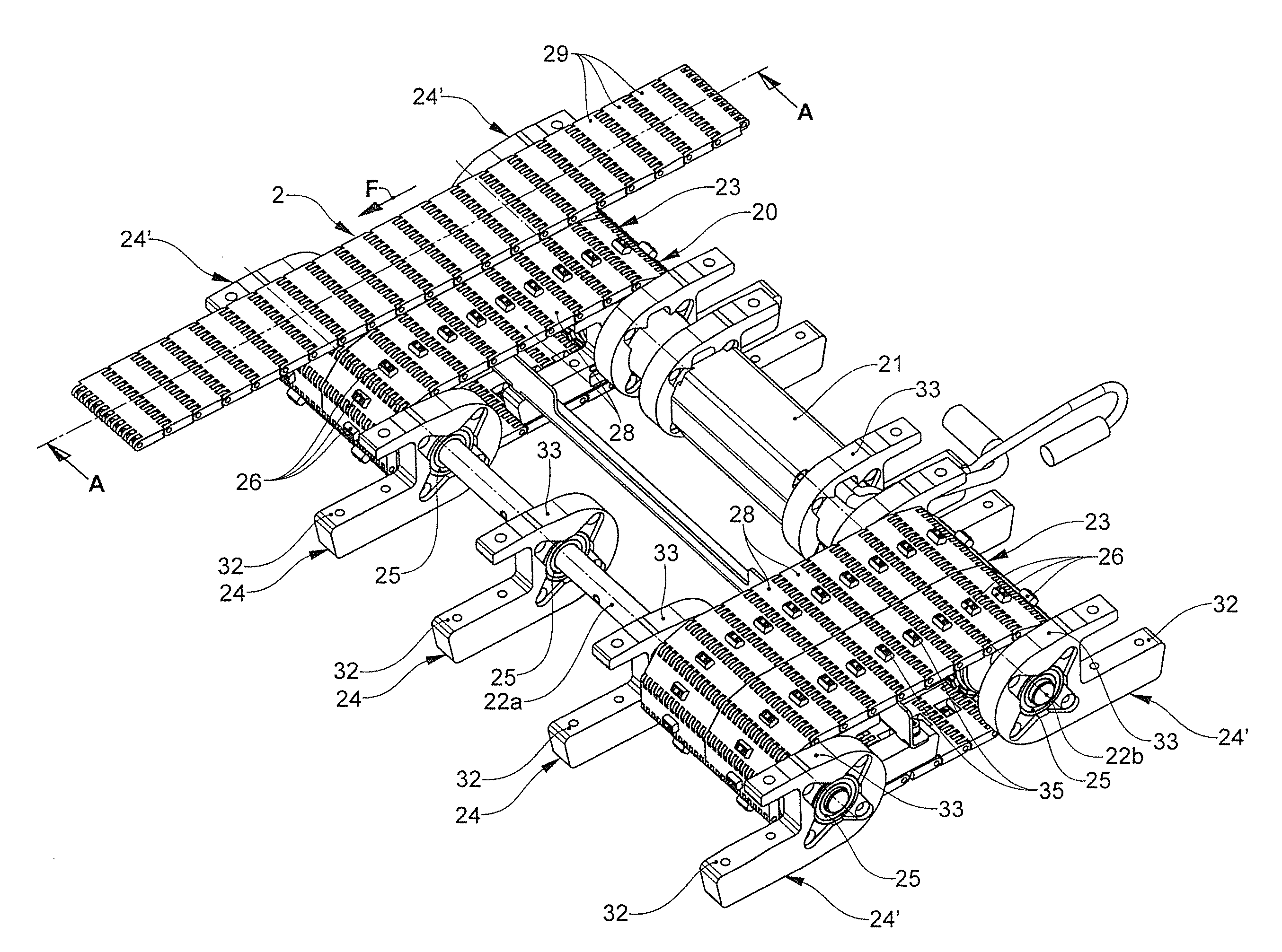
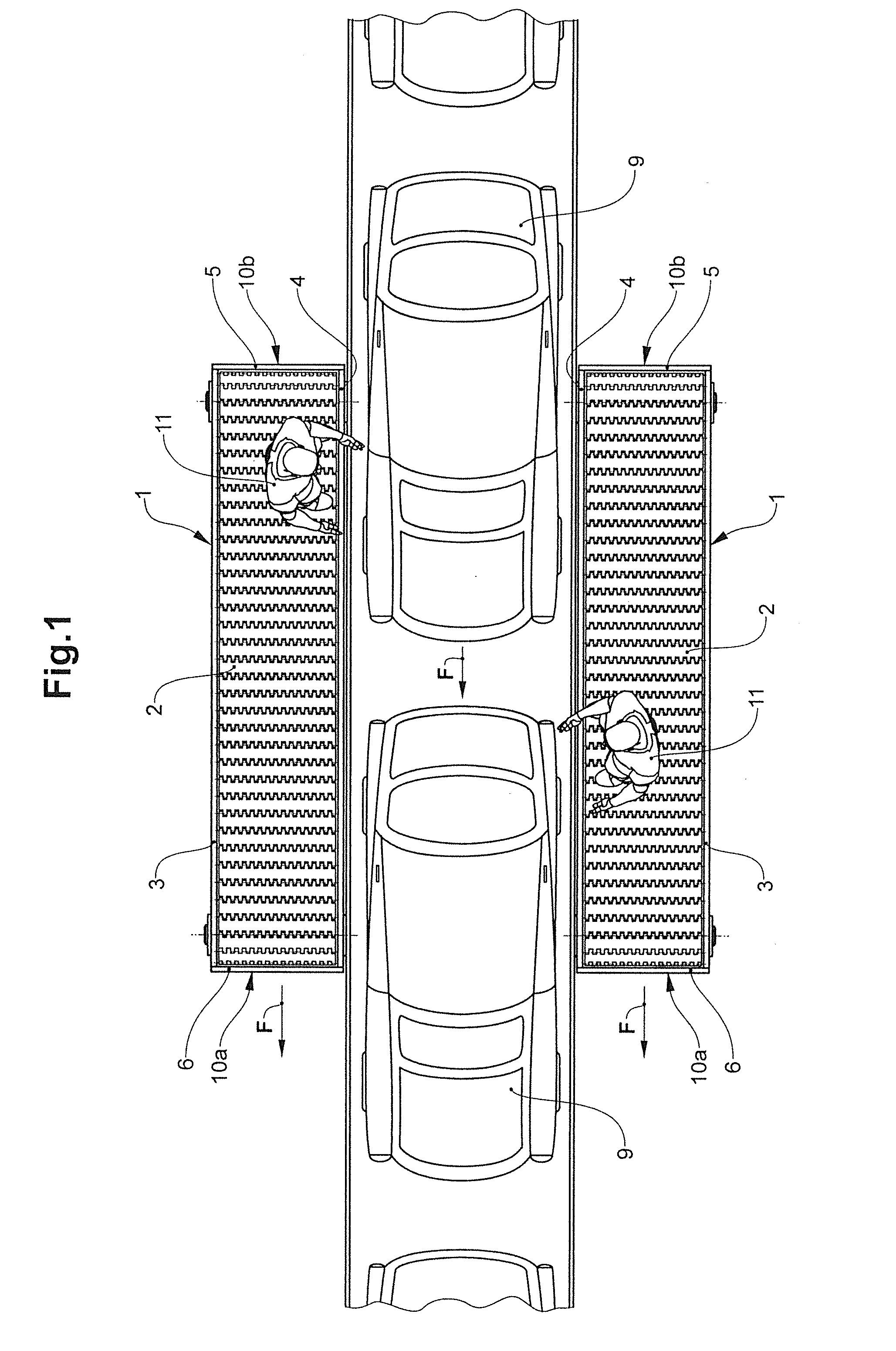
[0129]FIG. 1 shows an assembly line for the assembly of motor vehicles 9. The automobiles 9 are conveyed along assembly line in the conveying direction F, whilst working steps are simultaneously carried out on the automobile 9 by the workers 11. Conveying devices 1 according to the invention and in the embodiment of worker-rider belts are arranged on both sides of the assembly line. The worker-rider belts 1 include a circulating conveying element 2 in the form of a module belt chain. The module belt chain forms a level conveying surface, on which the workers 11 are co-moved with the automobiles 9 in the conveying direction F.

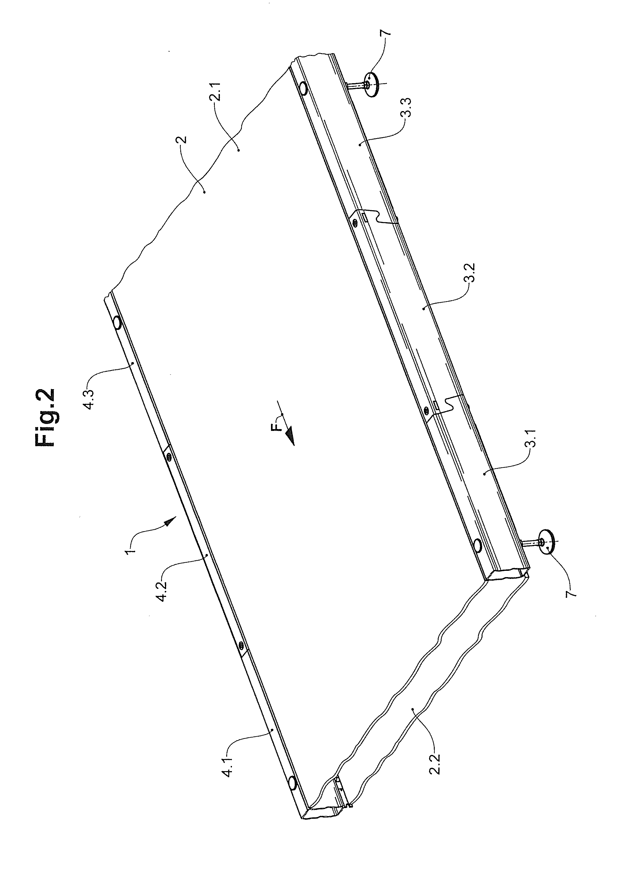
[0130]The module belt chain 2 is framed laterally by side closure beams 3, 4 and at the head-ends 10a, 10b by head-end transverse beams 5, 6.

[0131]The time available for the working steps on the automobiles 9 can be increased by way of co-moving workers 11 with the autom...


PUM


Abstract

A conveying device with an extensively extended conveying element that is led in a revolving manner along a conveying direction, is deflected at the head-ends of the conveying device and is laterally enclosed by side closure beams. The conveying device includes a drive device with a drive motor to drive the conveying element. The drive device is arranged between the two head-ends, between the side closure beams, and between the upper conveying section and the lower return section of the conveying element. The drive device includes a drive element that is arranged in a revolving manner about two deflection pivots spaced from one another in the conveying direction, and is driven by the drive motor. The drive element supports the upper conveying section of the conveying element, which is arranged at the top, and with this forms a contact fit for transmitting a drive force onto the conveying element.

Description

BACKGROUND OF THE INVENTION[0001]1. Field of the Invention[0002]The invention lies in the field of conveying technology and relates to a conveying device, including:[0003]two side closure beams that are spaced from one another and run along a conveying direction,[0004]an extensively extended conveying element, which is arranged in a circulating manner between the side closure beams and is with an upper conveying section and with a lower return section,[0005]two head-ends, which are spaced from one another in the conveying direction, wherein the conveying element is deflected at the head-ends in each case,[0006]a support arrangement arranged between the side closure beams and the head-ends, for supporting the conveying section,[0007]at least one drive device with at least one drive motor for the drive of the conveying element.[0008]2. Description of Related Art[0009]Conveying devices with a circulating, extensively extended conveying element, such as a conveying belt or mat chain, ar...

Claims


Application Information

Patent Timeline
Patent Type & Authority Applications(United States)
IPC IPC(8): B65G23/16B66B23/02B66B21/10B65G17/02B65G17/06
CPCB65G23/16B65G17/02B66B23/028B66B21/10B65G17/06B65G23/36B65G23/14
Inventor ALIESCH, ROBERT
Owner WRH WALTER REIST HLDG
Why Eureka
Try Eureka