Heavy-Duty Drive Arrangement and Mill Driven by the Same

a technology of drive arrangement and heavy duty, which is applied in the direction of differential gearing, toothed gearing, food science, etc., can solve the problems of disadvantageous consequences for mill design, and achieve the effect of low construction height of electric motor

Active Publication Date: 2011-06-23
F L SMIDTH & CO AS
View PDF2 Cites 3 Cited by
  • Summary
  • Abstract
  • Description
  • Claims
  • Application Information

AI Technical Summary

Benefits of technology

[0046]In one embodiment of the invention, at least a part of at least a bearing of the rotor is disposed with respect to a vertical coordinate within the extension range of the active range of the rotor. This results in a low constructional height of the electric motor.
[0047]In one embodiment of the invention, the rotor has a diameter which is larger than the vertical extension of the active part of the rotor. This enables a low constructional height of the electric motor.

Problems solved by technology

The inventor has found out that this has disadvantageous consequences for the design of the mill.

Method used


Image

  • Heavy-Duty Drive Arrangement and Mill Driven by the Same
  • Heavy-Duty Drive Arrangement and Mill Driven by the Same
  • Heavy-Duty Drive Arrangement and Mill Driven by the Same

Examples


Embodiment Construction

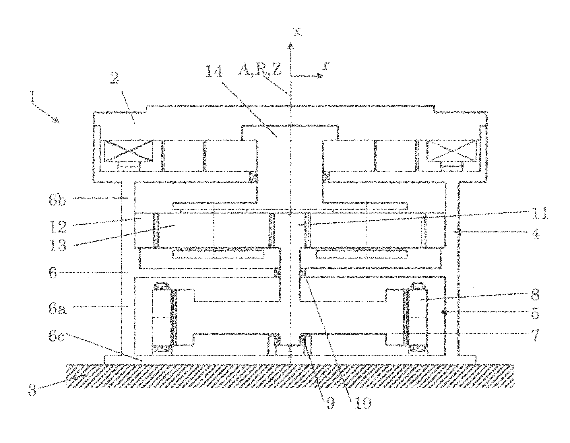
[0080]FIG. 1 schematically shows a sectional view of a drive arrangement 1 having an inner-rotor electric motor 5 connected directly to a one-stage planetary gearing 4. As in the other figures, too, toothings are not explicitly shown in FIG. 1.

[0081]The drive arrangement 1 has a housing 6, in which the electric motor 5 and the planetary gearing 4 are supported. The electric motor 5 has a stator 8 and a rotor 7. The rotor 7 is supported in a rotatable manner in an upper bearing 10 and a lower bearing 9. The stator 8 as well as the lower bearing 9 are supported on a bottom element 6c of the housing, which is supported on a foundation 3.

[0082]The electric motor 5 is disposed in a lower partial housing 6a of the housing 6, while the planetary gearing 4 is disposed in an upper partial housing 6b of the housing 6. Thereby the planetary gearing 4 is supported on the lower partial housing 6a.

[0083]The planetary gearing 4 has an internal gear 12, a sun gear 11 as well as several planet gear...


PUM


Abstract

A heavy-duty drive arrangement for a mill having a grinding bowl ratable about a vertical axis comprises a housing, an electric motor, and a gearing arrangement disposed in the housing and supported on the housing. The grinding bowl can be driven by means of the electric motor via the gearing arrangement. The electric motor is disposed below the gearing arrangement. The electric motor is integrated in the housing. Advantageously, the electric motor is supported on the housing particularly on a bottom element of the housing. The rotor can be connected directly, or via a coupling integrated in the rotor, to a gear of the gearing arrangement. The mill may be, for example, a roller bowl mill.

Description

CROSS-REFERENCE TO RELATED APPLICATIONS[0001]This application is the United States national stage under 35 U.S.C. §371 of International Application No. PCT / EP2008 / 060991, filed on Aug. 22, 2008. The entirety of this application is incorporated by reference herein.FIELD OF THE INVENTION[0002]The invention relates to mills, such as roller bowl mills, particularly cement mills and coal mills, as well as particularly to heavy-duty drive arrangements used therefore.BACKGROUND OF THE INVENTION[0003]In most of the present-day cement mills and coal mills, the roller bowl is driven via a gearing by a motor disposed laterally adjacent the gearing. In the case of such mills having a horizontally disposed roller bowl, the rotary motion of the motor is transmitted via a coupling to a bevel gear step, through which the rotary motion being initially about a horizontal axis is redirected to a vertical axis. In most cases a planetary gearing is used as the gearing, which moves the roller bowl via an...

Claims


Application Information

Patent Timeline
Patent Type & Authority Applications(United States)
IPC IPC(8): B02C15/00F16H1/02F16H1/28F16H57/04
CPCY10T74/19B02C15/006B02C15/00B02C15/06
Inventor RITTLER, STEFAN
Owner F L SMIDTH & CO AS
Why Eureka
Try Eureka