Relay

a technology of relays and relays, applied in the field of relays, can solve the problems of compact construction and the need to miniaturize the same even further, and achieve the effects of less space, reliable, long-term operation and convenient assembly

Active Publication Date: 2018-08-16
ELESTA GMBH OSTFILDERN DE ZWEIGNIEDERLASSUNG BAD RAGAZ
View PDF60 Cites 0 Cited by
  • Summary
  • Abstract
  • Description
  • Claims
  • Application Information

AI Technical Summary

Benefits of technology

[0013]The present invention furthers the development of the relay described last, such that it takes up less space. The invention proposes a miniaturized relay with a compact design, which ensures reliable, long-term operation. The present invention provides a relay which also works reliably when subjected to shaking. In addition, the relay is also be easy to assemble and optimally adjustable.
[0014]The invention relates to a relay, having an electromagnetic drive with a coil and a yoke, and having a movable armature which works together with the electromagnetic drive. The armature is mechanically connected via an actuating arrangement to a movable, electrical contact. A stationary, immobile partition is arranged between the electromagnetic drive and the contact. The electromagnetic drive is arranged on one side of the partition, and the movable electrical contact is arranged on the other side of the partition. The partition has an opening through which the mechanical actuation of the contact is carried out.
[0015]According to the invention, in the above-mentioned relay, the armature can pivot about an axis of rotation perpendicular to the plane of the iron core, and the actuating arrangement has an actuating arm which engages through the opening. This arrangement makes it possible to give the electromagnetic drive a lower constructed height than an arrangement in which the axis of rotation of the armature runs horizontal to the plane of the iron core. The coil body and coil are therefore rectangular in cross-section, wherein the width of the coil is at least 1.5 times, or at least 2 times, greater than the height.
[0016]Means are advantageously provided to push the armature against the yoke. These pressing means serve the function of holding a terminal portion of the armature on the end face of the yoke.
[0017]According to one embodiment, the armature is retained by an armature retainer attached to the yoke. This embodiment has the advantage that it is inexpensive and independent of the positioning of the electromagnetic drive relative to the partition or to the housing.
[0018]Advantageously, the armature retainer has a spring which pretensions the armature against the end face of the yoke. The spring in this case presses, against the end face of the yoke, the end portion of the armature about which the armature is pivoted. This is a simple and efficient construction.

Problems solved by technology

Although the relays described above are already very compact in construction, there exists a need to miniaturize the same even further.

Method used


Image

  • Relay
  • Relay
  • Relay

Examples


Embodiment Construction

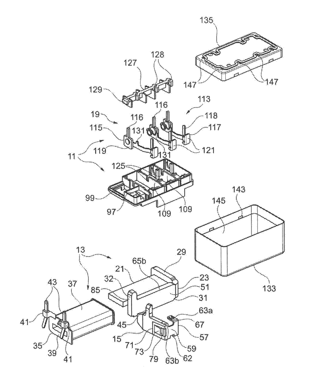
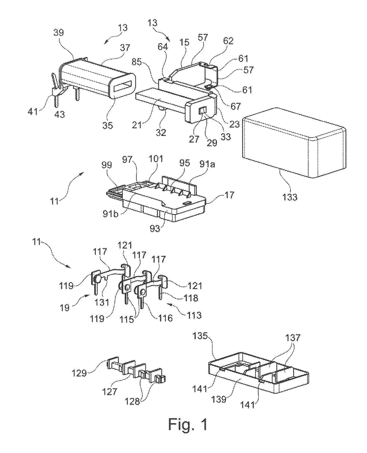
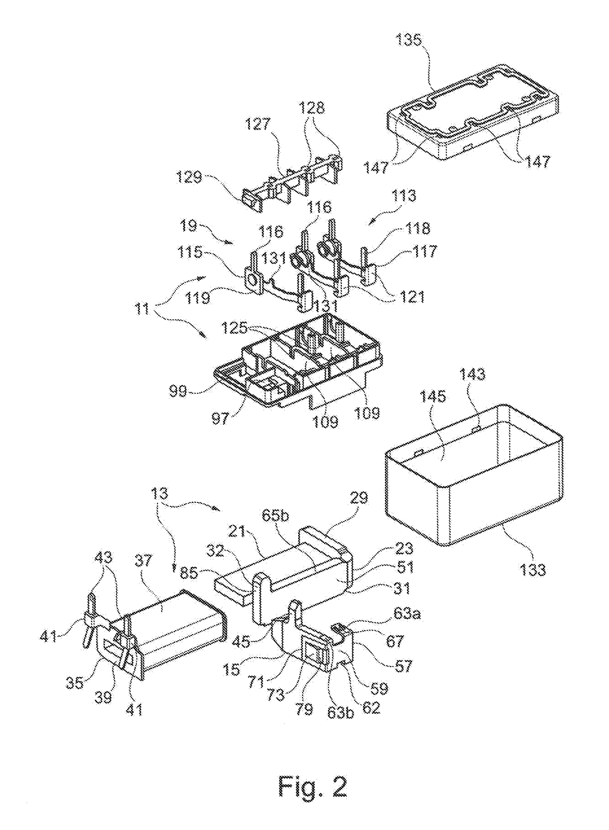
[0037]The essential components of the relay 11 shown in FIGS. 1 to 8 are an electromagnetic drive 13, an armature 15 which can be actuated by the electromagnetic drive 13, an intermediate base or partition 17, and a contact arrangement 19, which are described in more detail below in this order.

[0038]The electromagnetic drive 13 comprises a flat iron core 21 and a yoke 23 arranged on the same. Both the iron core 21 and the yoke 23 are made of one flat piece of ferromagnetic iron. The iron core 21 is rectangular when viewed from above, and a projection 27 is included (FIG. 8) in the center of a narrow side 25. The yoke 23 has an L-shape with a short limb 29 and a long limb 31, wherein the center planes of the two limbs 29, 31 are perpendicular to the center plane of the iron core 21. A positioning pin 32, projecting at a right angle, is included on the free end of the long limb 31, the function of which is described in more detail further below.

[0039]For the connection of the iron cor...


PUM


Abstract

invention relates to a relay, having an electromagnetic drive with a field coil arranged around an iron core which defines a plane, and a yoke. The electromagnetic drive works together with a movable armature which can switch a movable electrical contact via an actuating arrangement. The relay is accommodated in a housing, wherein an intermediate base and/or partition is included between the electromagnetic drive and the contact. The electromagnetic drive is arranged on one side of the partition, and the movable electrical contact is arranged on the other side of the partition. The partition has an opening through which the mechanical actuation of the contact is carried out. Because the armature is pivotable about an axis of rotation perpendicular to the plane of the iron core, the relay can have a lower constructed height than a conventional relay.

Description

CROSS-REFERENCE TO RELATED APPLICATION[0001]This application claims priority to Swiss Patent Application No. 00143 / 17 filed Feb. 8, 2017, the entirety of which is incorporated by this reference.FIELD OF THE INVENTION[0002]The invention relates to relays.PRIOR ART[0003]German patent application DE-OS-38 35 105 shows an electromagnetic relay having a gate-shaped iron core, the central portion of which is inserted into a groove of a field coil body with a press fit, wherein a field coil is wound around the field coil body and the iron core contained inside it. The electromagnetic drive works together with a U-shaped armature which has a foot part at the lower side of one of the end portions, and has, opposite thereto, a stop element which limits the pivot angle of the armature. In addition, a recess is included on the upper side of the armature, opposite the foot part. This recess works together with a projection in the upper right corner of the iron core which is intended to prevent t...

Claims


Application Information

Patent Timeline
Patent Type & Authority Applications(United States)
IPC IPC(8): H01H50/24H01H50/34H01H50/44H01H50/36H01H50/54
CPCH01H50/24H01H50/34H01H50/44H01H50/36H01H50/54H01H50/28H01H50/643
Inventor SEDENO MERCHAN, JUAN CRISTOBALGYORGY, ATTILASPATARO, ANTONINO
Owner ELESTA GMBH OSTFILDERN DE ZWEIGNIEDERLASSUNG BAD RAGAZ
Why Eureka
Try Eureka